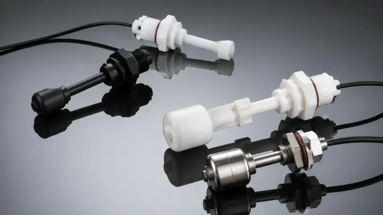
Level Switch Nozzle
Level Switch Nozzle
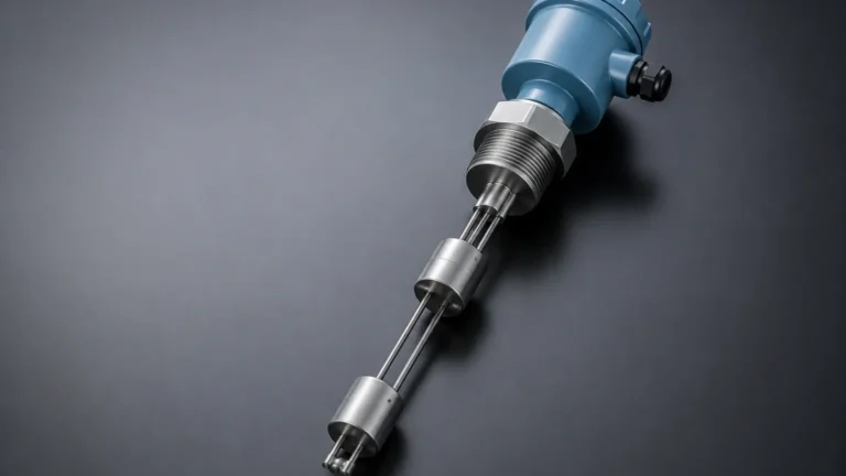
In industrial process control, the interface between a sensing instrument and the vessel it monitors is often as critical as the instrument itself. The level switch nozzle serves as this vital connection point. A nozzle is a cylindrical projection from a tank or pressure vessel, typically terminating in a flange or a threaded connection, designed to house a level sensor. While it may seem like a simple mechanical attachment, the geometry, length, and placement of the nozzle significantly influence the accuracy and reliability of Level Switches.
This guide explores the engineering principles of level switch nozzles, their interaction with various sensing technologies, and the best practices for selection and installation in B2B industrial environments.
The Role of the Nozzle in Level Detection
A level switch nozzle is more than just a mounting port; it is an extension of the process environment. Its primary functions include:
1. Structural Support: Providing a rigid, leak-proof mounting point that can withstand process pressures and temperatures.
2. Sensing Positioning: Determining the exact point at which the switch will trigger, ensuring the sensor probe or float is correctly immersed in the medium.
3. Protection: Shielding the sensor from mechanical stresses, such as high-velocity inflows or agitator-induced turbulence, depending on its design.
4. Accessibility: Allowing for the safe removal and maintenance of the instrument without requiring a full vessel shutdown, particularly when paired with isolation valves.
Failure to properly engineer the level switch nozzle can lead to "dead zones," where material becomes trapped and causes false readings, or signal interference in electronic sensors.
Measurement Principles and Nozzle Interaction
Before selecting a nozzle design, it is essential to understand how different level switch technologies interact with the mounting geometry. The nozzle must be designed to accommodate the specific physical or electronic requirements of the sensor.
Mechanical and Float Switches
Mechanical level switches, such as horizontal or vertical float switches, require a nozzle diameter ($D$) that allows the float to move freely. If the nozzle is too narrow, the float may strike the interior walls, leading to mechanical failure. Furthermore, the nozzle length ($L$) must be short enough to ensure the float can reach its activation point within the tank.
Vibrating Tuning Fork Switches
Vibrating switches rely on a piezoelectric crystal to vibrate a fork at its natural frequency. When the fork is immersed in a medium, the frequency changes, triggering the switch. The level switch nozzle must be wide enough to prevent the vibrating tines from touching the nozzle walls. If the nozzle is too long and the medium is viscous, the material may bridge between the tines and the nozzle wall, causing a "stuck" signal even when the level has dropped.
Capacitance and RF Admittance
These switches measure the change in electrical capacitance between the sensor probe and the vessel wall (or a reference probe). In this case, the nozzle acts as part of the electrical ground. The distance between the probe and the nozzle wall is critical; if the nozzle is too narrow, the base capacitance may be too high for the electronics to calibrate effectively.
Ultrasonic and Radar Point Level Switches
Non-contact or gap-style ultrasonic switches send signals across a small opening. For these, the nozzle must be designed to avoid internal reflections. A nozzle that is too long or has internal weld beads can create "noise," which the sensor might interpret as a high-level condition.
Engineering Specifications for Level Switch Nozzles
When designing or specifying a level switch nozzle, engineers must adhere to several key parameters to ensure process integrity and instrument performance.
Nozzle Dimensions: The L/D Ratio
A common rule of thumb in process engineering is the Length-to-Diameter ($L/D$) ratio. For most point level switches, the nozzle length should be kept as short as possible.
* Standard Nozzles: Typically, a nozzle length of 100 mm to 150 mm (4 to 6 inches) is preferred.
* Long Nozzles: If a nozzle must be longer (e.g., for insulated tanks), the diameter must increase proportionally to prevent material build-up and signal interference.
Materials of Construction
The nozzle material must be compatible with both the vessel and the process medium. Common materials include:
* Carbon Steel: Standard for non-corrosive oil and gas applications.
* Stainless Steel (304/316L): Preferred for water treatment, food and beverage, and chemical processing due to corrosion resistance.
* Exotic Alloys (Hastelloy, Monel): Used for highly aggressive chemical environments.
* Linings: For acidic applications, nozzles may be lined with PTFE or PFA to match the vessel lining.
Connection Types
* Flanged: The most common in industrial B2B applications. Flange ratings (e.g., ANSI 150#, 300# or DIN PN16, PN40) must match the vessel's design pressure.
* Threaded: Often used for smaller, low-pressure tanks. Common sizes include 1", 1.5", and 2" NPT or BSP threads.
* Sanitary (Tri-Clamp): Essential for pharmaceutical and food industries to ensure there are no crevices where bacteria can grow.
Selection Criteria: Matching the Nozzle to the Switch
The following table provides a practical reference for matching nozzle dimensions to common level switch technologies.
| Switch Type | Recommended Min. Nozzle Diameter ($D$) | Max. Recommended Nozzle Length ($L$) | Critical Consideration |
| :— | :— | :— | :— |
| Tuning Fork | 50 mm (2") | 150 mm (6") | Avoid build-up between tines and nozzle wall. |
| Float (Horizontal) | 80 mm (3") | 100 mm (4") | Ensure float arc clearance is maintained. |
| Capacitive | 40 mm (1.5") | 200 mm (8") | Consider the "inactive" length of the probe. |
| Rotary Paddle | 80 mm (3") | 150 mm (6") | Nozzle must allow paddle to rotate without friction. |
| Ultrasonic Gap | 50 mm (2") | 100 mm (4") | Minimize internal reflections/weld burrs. |
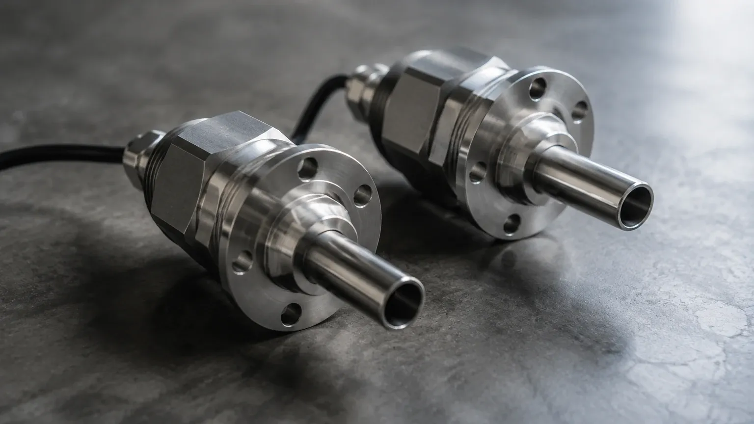
Installation Best Practices and Standoff Lengths
Proper installation of the level switch nozzle is as important as its design. Consider the following engineering guidelines:
1. Orientation
Nozzles for level switches can be mounted on the side (horizontal) or the top (vertical) of the vessel.
* Side-mounted nozzles should be sloped slightly (1-3 degrees) toward the tank if the medium is viscous, allowing the fluid to drain out of the nozzle and preventing false triggers.
* Top-mounted nozzles must be positioned away from the inflow stream to avoid false high-level alarms caused by splashing.
2. The Standoff/Dead Zone
A "standoff" occurs when the nozzle is longer than the active sensing element of the switch. For example, if a tuning fork switch has a 50 mm (2") insertion length but is mounted on a 150 mm (6") nozzle, the fork will remain inside the nozzle and never touch the actual liquid in the tank. Always ensure the insertion length of the Level Switches exceeds the nozzle length by at least 25 mm to 50 mm (1-2 inches).
3. Turbulence and Agitation
If the nozzle is located near an agitator, it may be subject to significant mechanical force. In these cases, the nozzle should be reinforced with a gusset, and the level switch may require a protective baffle or a stilling well to prevent damage to the probe.
4. Insulation and Heat Tracing
In outdoor applications or high-temperature processes, the nozzle can act as a heat sink. If the process medium solidifies at lower temperatures (like wax or heavy oil), the nozzle must be insulated or heat-traced to ensure the medium stays liquid within the nozzle, allowing the switch to function.
Common Risks and Limitations
Even a well-designed level switch nozzle can present challenges if environmental factors are ignored:
* Material Build-up (Bridging): In applications involving slurries or powders, material can pack into the nozzle. This creates a bridge that holds the switch in a triggered state even when the tank is empty.
* Corrosion at the Weld: The heat-affected zone (HAZ) of the nozzle-to-shell weld is a common point of failure. Regular NDT (Non-Destructive Testing) is recommended for high-pressure vessels.
* Internal Obstructions: Internal ladders, heating coils, or spray balls must be mapped before deciding on a nozzle location to avoid physical interference with the sensor probe.
* Vortex Formation: In fast-draining tanks, a vortex can pull air into a side-mounted nozzle, causing a level switch to trigger prematurely (low-level) or oscillate.
Frequently Asked Questions (FAQ)
Q: Can I use a nozzle that is smaller than the switch probe if I use a reducer?
A: It is generally not recommended. Reducers create internal shoulders where material can collect and air can become trapped. It is best to match the nozzle diameter to the instrument's mounting requirements.
Q: How do I handle a level switch nozzle on a plastic or fiberglass (FRP) tank?
A: Plastic tanks lack the grounding reference required by capacitive switches. In these cases, the nozzle should include a grounding ring or a dual-probe switch should be used where the second probe acts as the ground.
Q: What is the maximum pressure a standard flanged nozzle can handle?
A: This depends on the flange rating and material. For example, a 316 Stainless Steel Class 150 flange is typically rated for approximately 19 bar (275 psi) at ambient temperature, but this rating drops significantly as temperature increases. Always consult ASME B16.5 or equivalent standards.
Q: Should the nozzle be flush with the internal wall of the tank?
A: For most applications, yes. A flush-mounted nozzle prevents solids from accumulating at the entry point. However, in some heavy-sediment applications, a nozzle that extends slightly into the tank (a "re-entrant" nozzle) may be used to ensure the sensor is measuring the representative fluid and not the sludge layer on the wall.
Conclusion
The level switch nozzle is a fundamental component of industrial level measurement systems. By carefully considering the $L/D$ ratio, material compatibility, and the specific requirements of the sensing technology, engineers can prevent the most common causes of instrument failure. Whether you are specifying Level Switches for a new project or troubleshooting an existing installation, the nozzle geometry should always be the first point of inspection for ensuring reliable point level detection.