Level Switch P&id Symbol
Level Switch P&id Symbol
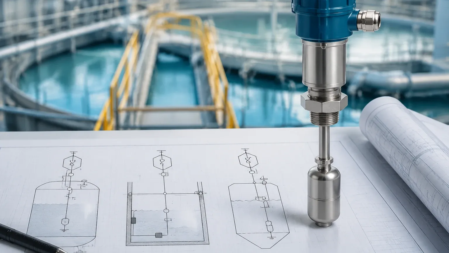
In the complex world of process engineering and industrial automation, the Piping and Instrumentation Diagram (P&ID) serves as the primary blueprint for system design, safety, and operation. Among the most critical components represented on these diagrams are Level Switches, which provide point-level detection to prevent tank overflows, protect pumps from dry running, and manage automated filling cycles. Understanding the specific level switch p&id symbol is essential for engineers, technicians, and plant operators to ensure that the physical installation matches the design intent and safety requirements of the facility.
As a professional manufacturer of industrial level measurement instruments, Welk provides a wide range of switching technologies designed to meet the rigorous demands of water treatment, chemical processing, and oil and gas industries. This guide explores the standardized symbology used in P&IDs and the measurement principles that dictate which hardware should be specified for a given application.
The Role of Level Switches in Process Control
Level switches are discrete sensors. Unlike continuous level transmitters that provide a constant 4-20mA or digital signal representing the exact level, a level switch changes state (from open to closed or vice versa) when a specific liquid or solid level is reached. This change in state is typically used to trigger an alarm, start or stop a pump, or open/close a valve.
On a P&ID, these instruments are not merely represented as generic blocks. They follow the ISA-5.1 (International Society of Automation) standards, which use a combination of circles, lines, and letter codes to convey the instrument's function, location, and connectivity.
Understanding the Level Switch P&ID Symbol
The level switch p&id symbol is composed of several elements that define its role in the process loop. According to ISA standards, the symbol is usually a circle (often called a "bubble") containing a letter code.
Letter Designations
In the standard notation, the first letter identifies the measured variable, which for level is L. The succeeding letters define the function of the instrument. Common designations include:
* LS (Level Switch): The general designation for a switch.
* LSH (Level Switch High): A switch designed to actuate when the level rises to a high setpoint.
* LSL (Level Switch Low): A switch designed to actuate when the level drops to a low setpoint.
* LSHH (Level Switch High-High): Typically used for emergency high-level shutdowns or overfill protection.
* LSLL (Level Switch Low-Low): Typically used for emergency low-level shutdowns to protect equipment like heaters or pumps.
Graphic Symbols and Lines
The circle itself provides information about where the instrument is located:
* No horizontal line: The switch is located in the field, mounted directly on the vessel or pipe.
* Single solid horizontal line: The switch is located in a primary control room or accessible control panel.
* Double solid horizontal line: The switch is located in a secondary or local control panel.
* Dashed horizontal line: The switch is located in a place not easily accessible to the operator, or it represents a software-based switch within a Distributed Control System (DCS).
Measurement Principles and Technology Selection
Before selecting a level switch p&id symbol for a project, engineers must decide on the physical measurement principle. Welk offers several technologies, each suited to different process conditions.
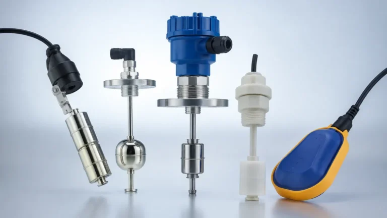
1. Float Level Switches
Float switches operate on the principle of buoyancy. A float, containing a magnet, moves with the liquid level. When it reaches a reed switch or microswitch within the stem, it triggers a change in state. These are simple, reliable, and cost-effective for clean liquids.
2. Tuning Fork (Vibrating) Level Switches
The tuning fork switch uses a piezoelectric crystal to vibrate a metal fork at its natural frequency. When the fork is submerged in liquid or covered by solids, the frequency changes. The electronics detect this shift and trigger the switch. This technology is highly resistant to turbulence, bubbles, and foam.
3. Capacitance Level Switches
These switches measure the change in electrical capacitance between the sensor probe and the tank wall (or a reference probe). As the medium covers the probe, the dielectric constant changes, altering the capacitance. These are excellent for both liquids and solids but require calibration based on the medium's dielectric properties.
4. Ultrasonic Gap Switches
An ultrasonic gap switch consists of two sensors separated by a small gap. One sensor transmits an ultrasonic signal, and the other receives it. When the gap is filled with liquid, the signal transmits efficiently; when it is filled with air or gas, the signal is attenuated. This provides a reliable non-contact (with moving parts) method for point level detection.
5. Hydrostatic Level Switches
While often used for continuous measurement, hydrostatic pressure can be used for switching. A diaphragm senses the pressure exerted by the liquid column above it. When the pressure reaches a setpoint corresponding to a specific height, the switch actuates. This is common in deep wells or large water tanks.
Practical Selection Table for Level Switches
When translating a level switch p&id symbol into actual hardware, use the following table to match the technology to the application requirements.
| Technology | Suitable Media | Max Temp (°C/°F) | Max Pressure (Bar/PSI) | Key Advantage |
| :— | :— | :— | :— | :— |
| Float Switch | Clean Liquids | 150°C / 302°F | 40 Bar / 580 PSI | Simple, No Power Required |
| Tuning Fork | Liquids, Slurries, Powders | 250°C / 482°F | 64 Bar / 928 PSI | No calibration, foam resistant |
| Capacitance | Liquids, Solids, Granules | 200°C / 392°F | 100 Bar / 1450 PSI | High pressure/temp capability |
| Ultrasonic Gap | Acids, Alkalis, Oils | 120°C / 248°F | 20 Bar / 290 PSI | No moving parts, reliable |
| Conductivity | Conductive Liquids | 100°C / 212°F | 10 Bar / 145 PSI | Very low cost, multi-point |
Installation Considerations and Best Practices
The physical installation of a level switch must align with the logic indicated by the level switch p&id symbol. If a P&ID shows an LSHH, it must be mounted at the highest physical point required for safety shutdown.
Nozzle Length and Orientation
For tuning fork and ultrasonic switches, the "dead zone" or nozzle length must be considered. If the nozzle is too long, the medium may get trapped, causing the switch to stay in the "active" state even after the level has dropped. Standard nozzles are typically 50mm to 100mm (2 to 4 inches) in length.
Turbulence and Agitation
In tanks with agitators or high-velocity inflow, float switches may bounce, leading to "chattering" of the relay. In these environments, tuning fork switches or switches with a built-in time delay (typically 1 to 5 seconds) are preferred to ensure a stable signal.
Mounting Position
* Vertical Mounting: Common for float switches and multi-point conductivity probes. It allows for multiple setpoints on a single stem.
* Horizontal Mounting: Common for tuning fork and capacitance switches. This allows for precise point detection at a specific vessel height.
Limitations and Common Risks
While level switches are fundamental to process safety, they are not without limitations. Engineers should be aware of the following risks when specifying equipment based on a level switch p&id symbol:
1. Coating and Build-up: In sticky or viscous media, material can build up on the sensor (especially capacitance or tuning fork probes). While many Welk switches feature "active shield" technology to ignore build-up, extreme cases can still lead to false triggers.
2. Specific Gravity Changes: Float switches are dependent on the density of the liquid. If the process fluid changes from water (SG 1.0) to a light hydrocarbon (SG 0.7), the float may no longer buoy correctly, failing to actuate the switch.
3. Mechanical Wear: Any switch with moving parts, such as a float or a paddle switch, is subject to mechanical fatigue over time. Regular maintenance and testing (Proof Testing) are required for safety-critical loops (SIL rated).
Frequently Asked Questions (FAQ)
What is the difference between an LS and an LT on a P&ID?
An LS (Level Switch) is a point-level device that provides a discrete On/Off signal. An LT (Level Transmitter) provides a continuous signal (like 4-20mA) representing the total range of the level in the tank.
How is a fail-safe level switch p&id symbol represented?
The P&ID symbol itself often does not show the fail-safe state (Normally Open vs. Normally Closed). This is typically detailed in the instrument data sheet or the logic diagram. However, the designation LSHH often implies a fail-safe "de-energize to trip" logic for safety.
Can one level switch p&id symbol represent multiple setpoints?
If a single physical instrument has multiple switch points (like a multi-float stem), the P&ID will often show multiple bubbles (LSL, LSH) connected to a single vessel entry point to indicate that one process connection serves multiple functions.
What units are used for level switch setpoints?
In international projects, setpoints are typically defined in millimeters (mm) or meters (m) from the bottom of the tank (datum line). In the United States, inches (in) or feet (ft) are commonly used. For example, an LSH might be set at 2500mm (approx. 98.4 inches).
Conclusion
Accurately interpreting and implementing the level switch p&id symbol is a cornerstone of safe and efficient industrial design. Whether you are managing a simple water storage tank or a high-pressure chemical reactor, selecting the right switching technology—be it float, tuning fork, or capacitance—ensures that your process remains within its designed boundaries.
Welk continues to support global industries with a comprehensive portfolio of Level Switches and measurement solutions, backed by rigorous quality control and technical expertise. When designing your next P&ID, ensure that your instrument selection accounts for the physical properties of your media and the critical safety requirements of your application.