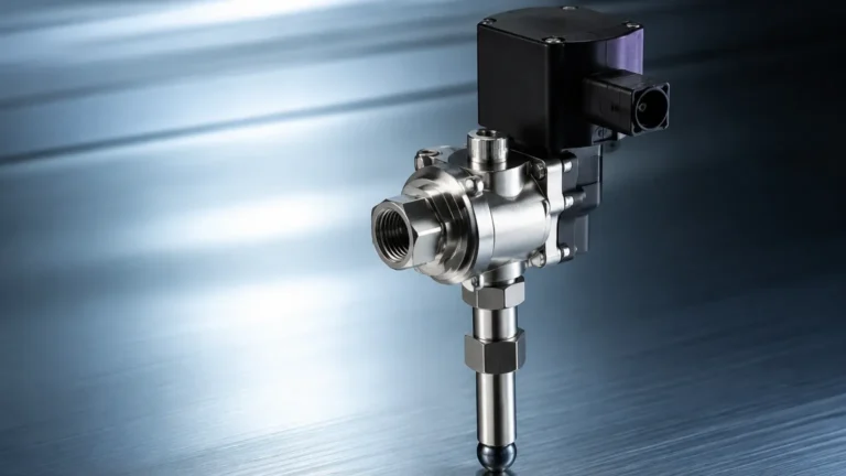
Level Switch P&id
Level Switch P&id
In the realm of process engineering and industrial automation, the Piping and Instrumentation Diagram (P&ID) serves as the fundamental blueprint for plant design. Among the various components detailed in these diagrams, Level Switches play a critical role in safety, inventory management, and process control. Understanding how to correctly represent and specify a level switch p&id is essential for engineers, technicians, and system integrators to ensure operational reliability and regulatory compliance.
A level switch is a discrete point level sensor designed to detect the presence or absence of a substance—liquid, powder, or granulated solid—at a specific height within a vessel or pipe. Unlike continuous level transmitters that provide a constant stream of data, a level switch provides a binary output (on/off) used to trigger alarms, start or stop pumps, or open and close valves.
Principles of Point Level Measurement
Before detailing the representation of a level switch p&id, it is necessary to understand the physical principles that govern these devices. Choosing the right technology is the first step in ensuring the P&ID reflects a functional and reliable system.
Vibrating Fork (Tuning Fork) Switches
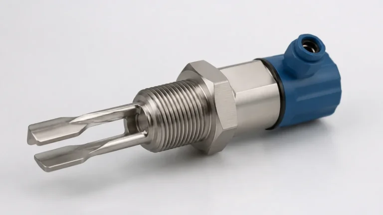
These switches utilize a fork-shaped sensing element that vibrates at its natural resonant frequency using piezoelectric crystals. When the fork is submerged in a medium, the frequency changes. The internal electronics detect this shift and toggle the output. They are highly reliable for liquids and solids and are largely unaffected by flow, turbulence, or bubbles.
Float and Magnetic Level Switches
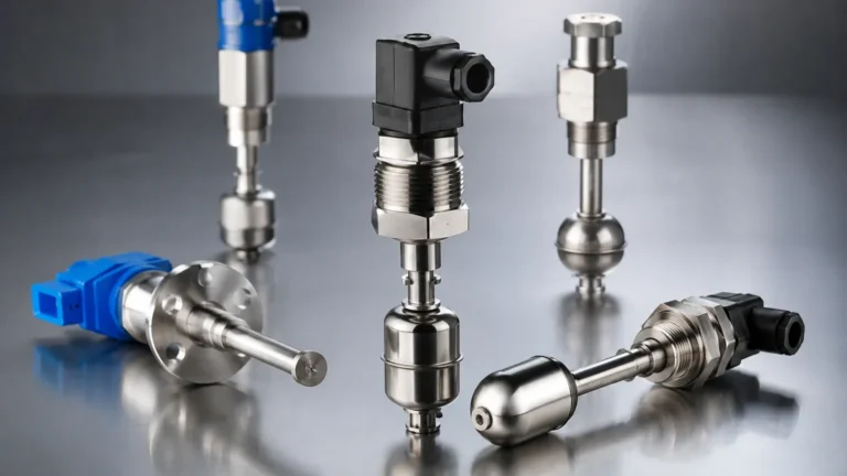
Operating on the principle of buoyancy, a float moves with the liquid level. In magnetic designs, the float contains a permanent magnet that actuates a reed switch located inside a sealed stem. These are cost-effective and simple but are susceptible to mechanical wear and fouling in dirty or viscous liquids.
Capacitance Level Switches
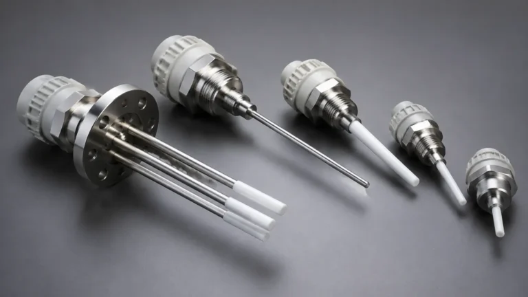
The sensor and the vessel wall (or a second probe) act as two plates of a capacitor. As the material level rises and displaces air, the dielectric constant changes, altering the capacitance. This change is measured to determine the presence of the material. These are excellent for powders and granules but require calibration for different media.
Ultrasonic Point Level Switches
These devices use a gap between two ultrasonic transducers. When the gap is filled with liquid, ultrasonic waves travel across it; when the gap is empty (filled with air or gas), the waves are attenuated. This technology is ideal for non-contact applications or where mechanical moving parts are undesirable.
Understanding Level Switch P&ID Symbols and Designations
The representation of level switches in a P&ID follows standardized conventions, primarily those established by the International Society of Automation (ISA), specifically ISA-5.1. These standards ensure that any engineer, regardless of their location, can interpret the control logic and hardware requirements of the system.
Letter Designations
In a level switch p&id, the device is typically identified by a circle (often called a "bubble") containing a letter code. The standard code for a level switch is LS. This is further refined based on the function:
* LSH (Level Switch High): Triggers when the level reaches a high setpoint, often used for tank filling control.
* LSL (Level Switch Low): Triggers when the level drops below a minimum point, often used to prevent pump cavitation (run-dry protection).
* LSHH (Level Switch High-High): A safety-critical switch set above the LSH to prevent overfilling and potential environmental hazards.
* LSLL (Level Switch Low-Low): A safety-critical switch set below the LSL to ensure a minimum head of liquid or to protect equipment.
Graphical Symbols
The "bubble" symbol itself provides information about the instrument's location:
* No line inside the circle: The switch is mounted locally in the field.
* Solid horizontal line: The switch or its indicator is located on a primary control panel accessible to the operator.
* Dashed horizontal line: The switch is located behind a panel or in a restricted area.
* Double horizontal line: The switch is located on a secondary or local control panel.
In a level switch p&id, the connection between the process vessel and the switch bubble is represented by a solid line, indicating a physical process connection (e.g., a nozzle or flange). The output from the switch to the control system (PLC/DCS) is represented by a dashed line with cross-marks, signifying an electrical signal.
Selection Criteria for Level Switches in Process Design
When documenting a level switch p&id, the engineering specification must align with the physical realities of the process. Engineers must evaluate several criteria to ensure the selected switch performs as intended.
| Criteria | Considerations |
| :— | :— |
| Media Type | Is it a liquid, slurry, or solid? Is it corrosive, abrasive, or conductive? |
| Process Conditions | What are the maximum and minimum operating pressures (bar/psi) and temperatures (°C/°F)? |
| Vessel Geometry | Are there internal obstructions like agitators, baffles, or heating coils? |
| Installation Orientation | Will the switch be mounted vertically from the top or horizontally from the side? |
| Output Requirements | Does the system require a dry contact relay, a transistor (PNP/NPN), or a digital protocol like IO-Link? |
| Hazardous Areas | Does the environment require explosion-proof (Ex d) or intrinsically safe (Ex i) certifications? |
Installation Considerations and Best Practices
The accuracy of a level switch p&id is only as good as its physical implementation. Improper installation is a leading cause of instrument failure.
Nozzle Design
The nozzle on which the switch is mounted must be of sufficient diameter to allow for the sensing element to pass through without interference. For vibrating fork switches, the nozzle length should not exceed the "dead zone" of the sensor to prevent false triggers caused by material buildup inside the nozzle.
Turbulence and Agitation
If a tank has an agitator, the level switch should be positioned away from the vortex and the blades. In cases of extreme turbulence, a stilling well (a perforated pipe) may be required to provide a stable environment for the sensor. This must be clearly indicated on the P&ID.
Mounting Orientation
* Top Mounting: Ideal for LSHH and LSH. Requires longer probe lengths (e.g., 500 mm to 3000 mm) to reach the desired setpoints.
* Side Mounting: Common for LSL and LSLL. Allows for short-insertion probes, reducing costs and mechanical stress.
Electrical Safety
All level switches should be installed with a drip loop in the conduit to prevent moisture from entering the housing. Furthermore, the P&ID should reflect the fail-safe state of the switch. A "Normally Closed" (NC) configuration is typically preferred for safety circuits, as a wire break will trigger an alarm, alerting the operator to a fault.

Technical Comparison Table: Technology Selection
| Technology | Best Application | Limitations | Typical P&ID Label |
| :— | :— | :— | :— |
| Vibrating Fork | General purpose liquid/solids | Viscous liquids (>10,000 cP) | LSH / LSL |
| Float Switch | Clean water, oil | Moving parts, fouling | LSL / LSLL |
| Capacitance | Powders, interface detection | Requires calibration | LSH / LSHH |
| Ultrasonic Gap | High-precision liquid detection | Bubbles/Foam interference | LSH / LSL |
| Conductivity | Conductive liquids (acids/bases) | Only for conductive media | LSH / LSL |
Limitations and Common Risks
While level switches are robust, they are not infallible. Engineers must account for the following risks during the design phase:
1. Coating and Buoyancy: In sticky or crystallizing media, material can build up on the sensor. For float switches, this may prevent movement. For tuning forks, it may dampen the vibration, leading to a false "covered" signal. Choosing a switch with "active shield" technology or a polished surface can mitigate this.
2. Foam Interference: Some technologies, like ultrasonic or certain capacitance switches, may struggle to distinguish between a layer of foam and the actual liquid level. If foam is expected, a tuning fork or a heavy-duty float may be more appropriate.
3. Pressure Spikes: In high-pressure systems, sudden surges can damage fragile sensing elements. Always verify that the switch's pressure rating (e.g., 40 bar / 580 psi) exceeds the maximum design pressure of the vessel.
4. Electromagnetic Interference (EMI): Switches installed near high-power motors or variable frequency drives (VFDs) may experience signal noise. Shielded cabling and proper grounding are essential.
Frequently Asked Questions (FAQ)
Q: What is the difference between LSH and LSHH on a P&ID?
A: LSH (Level Switch High) is typically used for process control, such as stopping a pump when a tank is full. LSHH (Level Switch High-High) is a dedicated safety switch, often wired to an Emergency Shutdown (ESD) system, designed to act only if the LSH fails to stop the process.
Q: Can I use a continuous level transmitter as a level switch?
A: Yes, modern transmitters (like radar or ultrasonic) often have programmable relay outputs that can act as switches. On a P&ID, this would be represented as a Level Transmitter (LT) with an associated Level Alarm (LAH/LAL) or software-based switch (LS).
Q: How do I represent a side-mounted level switch vs. a top-mounted one?
A: In a level switch p&id, the physical mounting is shown by the line connecting the instrument bubble to the vessel. If the line enters the side of the vessel symbol, it is side-mounted. If it enters from the top, it is top-mounted.
Q: What does the "S" in LSH stand for?
A: The "S" stands for "Switch," indicating a discrete output. This distinguishes it from "I" (Indicator) or "T" (Transmitter).
By meticulously detailing the level switch p&id and selecting the appropriate technology for the application, engineers can build safer, more efficient industrial processes. Whether protecting a pump from running dry or preventing a hazardous chemical spill, the humble level switch remains a cornerstone of industrial instrumentation.