Level Switch Calibration
Level Switch Calibration
In industrial process control, point level detection serves as a critical safeguard for equipment and personnel. While continuous level measurement provides a constant stream of data regarding the volume or height of a substance, level switches act as the final line of defense, triggering alarms, stopping pumps, or opening valves when a specific threshold is reached. Ensuring these devices operate at the precise intended point requires a thorough understanding of level switch calibration and the underlying physics of each sensing technology.
Level switch calibration differs significantly from the calibration of continuous transmitters. For a transmitter, calibration involves mapping a range of physical levels (e.g., 0 to 10 meters) to a proportional output signal (e.g., 4-20 mA). For Level Switches, calibration typically refers to the adjustment of the switching point, the sensitivity to the medium, and the management of hysteresis to prevent rapid cycling. This guide explores the technical requirements for maintaining accuracy in point level detection across various industrial applications.
Measurement Principles and Their Impact on Calibration
Before performing any level switch calibration, an engineer must understand the specific measurement principle of the device. Each technology interacts with the process medium differently, which dictates how the switch is adjusted and maintained.
Float and Displacer Switches
These mechanical switches rely on buoyancy. A float stays on the surface of the liquid, moving an internal magnet or mechanical linkage to actuate a switch. Calibration for these devices is primarily physical; it involves setting the stop collars on a rod or adjusting the cable length of a suspended float. The density (specific gravity) of the liquid is the primary variable. If the liquid density changes significantly from the design specification, the float may sit higher or lower in the liquid, shifting the actual switching point.
Vibrating Point Level Switches (Tuning Forks)
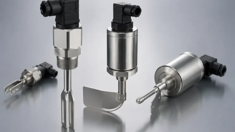
These sensors use a piezo-electric crystal to vibrate a fork at its natural resonant frequency in the air. When the fork is submerged in a liquid or solid, the frequency changes. The electronics detect this shift and trigger the relay. Calibration here is often electronic, involving sensitivity settings to distinguish between the actual product and heavy coating or foam.
Capacitive Level Switches
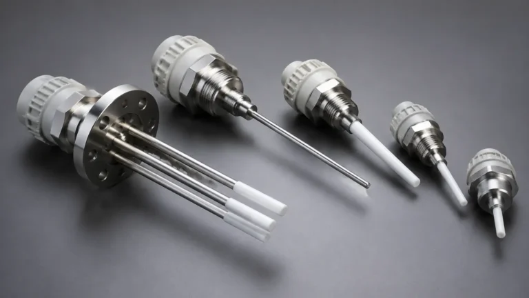
Capacitance switches treat the sensor probe and the tank wall (or a reference probe) as two plates of a capacitor. The process material acts as the dielectric. As the material covers the probe, the capacitance increases. Level switch calibration for capacitive sensors is vital because it must account for the dielectric constant of the material. Adjustments are made to the "set point" potentiometer or digital interface to ensure the switch ignores build-up on the probe while still detecting the bulk material.
Ultrasonic and Optical Switches
Ultrasonic switches use high-frequency sound waves to detect the presence of a medium, while optical switches use infrared light refraction. These are generally "gap" sensors. Calibration for these units often involves verifying the signal strength and ensuring that the sensor is not being fooled by bubbles in liquids or dust in silos.
The Level Switch Calibration Process
Level switch calibration is the process of verifying and adjusting the point at which the switch changes state (from open to closed or vice versa). While some modern digital switches are "plug-and-play," many industrial environments require manual verification to meet safety integrity level (SIL) requirements.
1. Bench Calibration vs. Field Calibration
Bench calibration is performed in a controlled laboratory environment using a calibration cylinder. This allows for precise measurement of the switching point relative to a reference mark on the sensor body. Field calibration, however, is performed in situ. It is often more accurate for the specific application because it accounts for the actual process temperature, pressure, and vessel geometry.
2. Setting the Switching Point
For most electronic switches, the calibration procedure follows these general steps:
* Dry State Verification: Ensure the switch is in its "normal" state when the vessel is empty or the level is below the probe.
* Wetting the Sensor: Raise the level of the process medium (or a simulant with similar physical properties) until it reaches the desired trip point.
* Adjustment: Adjust the sensitivity or set-point screw until the output changes. In digital systems, this may involve a "teach-in" button where the device records the current capacitance or frequency as the "Full" state.
* Hysteresis Adjustment: Define the "reset" point. Hysteresis (or differential) is the distance between the switch-on point and the switch-off point. Proper level switch calibration ensures the differential is wide enough to prevent "chattering" caused by surface turbulence or ripples.
3. Sensitivity and Coating Rejection
In applications involving viscous liquids like resins or food products, material can stick to the probe. If the sensitivity is set too high, the switch will indicate a "high level" even after the tank has been emptied. Calibration must find the balance where the switch ignores the residual coating but reacts immediately to the rising bulk liquid.
Practical Selection Table for Level Switches
Choosing the right technology is a prerequisite for successful calibration. The following table summarizes common technologies and their calibration considerations.
| Technology | Best For | Calibration Complexity | Key Variable to Confirm |
| :— | :— | :— | :— |
| Float Switch | Water, Oils, Clean Liquids | Low (Mechanical) | Liquid Density (Specific Gravity) |
| Vibrating Fork | General Purpose, Liquids/Solids | Low (Electronic) | Media Density & Viscosity |
| Capacitance | Chemicals, Slurries, Interface | Moderate | Dielectric Constant (εr) |
| Conductivity | Conductive Liquids (Water-based) | Low | Liquid Conductivity (μS/cm) |
| Hydrostatic | Deep Tanks, Sumps | Moderate | Density & Temperature |
Installation Considerations for Accurate Switching
Even a perfectly calibrated switch will fail if the installation is flawed. Engineering teams must consider the following during the design and installation phase:
* Nozzle Length: For capacitive and ultrasonic switches, the nozzle (the pipe section where the switch is mounted) should not be so long that it traps air or material, leading to false readings.
* Turbulence and Agitators: If a tank has an agitator, the switch should be installed in a location where the vortex or splashing does not cause premature actuation. Stilling wells are often recommended for float switches in turbulent tanks.
* Orientation: Vibrating forks should be oriented so that the liquid can easily drain off the blades. Typically, this means the flat surfaces of the forks are vertical. For solids, the forks should be shielded from the direct flow of falling material to prevent mechanical damage.
* Wiring and Grounding: Capacitive switches require a solid ground reference to the metal tank wall. In plastic or lined tanks, a grounding rod or plate must be used, or the calibration will drift significantly as environmental conditions change.

Common Risks and Limitations
During level switch calibration and operation, several factors can introduce errors:
1. Temperature Shifts: Extreme temperatures can change the dielectric constant of a liquid or the physical dimensions of a mechanical float arm. If a switch is calibrated at 20°C but operates at 80°C, the trip point may shift.
2. Pressure Effects: High pressure can increase the density of gases or vapors above a liquid, which may interfere with ultrasonic or certain sensitive vibrating switches.
1. Build-up and Scaling: Over time, minerals or process materials can form a hard scale on the sensor. Regular maintenance schedules should include a check of the calibration to ensure the build-up hasn't compromised the switching logic.
1. Electromagnetic Interference (EMI): In environments with large motors or variable frequency drives (VFDs), electrical noise can interfere with the low-voltage signals in capacitive or ultrasonic sensors. Shielded cabling is essential.
Frequently Asked Questions (FAQs)
Q: How often should level switch calibration be verified?
A: For non-critical applications, an annual check is usually sufficient. However, for safety-instrumented systems (SIS) or high-level overfill protection, a proof test and calibration verification should be performed every 3 to 6 months, depending on the risk assessment.
Q: Can I calibrate a level switch without filling the tank?
A: For some technologies, yes. Many modern vibrating forks and capacitive switches have a "test" function that simulates a covered state. However, a "wet test" is always the gold standard for verifying the actual physical switching point.
Q: What is the difference between a normally open (NO) and normally closed (NC) configuration?
A: This refers to the state of the switch when it is not actuated (e.g., when the tank is empty). In many safety applications, an NC configuration is preferred for high-level alarms because if a wire breaks, the system will fail into an alarm state (fail-safe).
Conclusion
Level switch calibration is a fundamental aspect of industrial maintenance that ensures the reliability of point level detection systems. By understanding the specific measurement principles—whether they are based on buoyancy, frequency, or capacitance—operators can accurately set trip points that protect equipment and optimize processes. Selecting the correct Level Switches for the specific medium and environment is the first step toward a stable and easily maintainable system. Regular verification, proper installation, and an awareness of process variables like density and dielectric constants will ensure that these critical components perform their function when they are needed most.