Liquid Level Switches
Liquid Level Switches
In industrial process automation, point-level detection serves as a critical safeguard for inventory management, pump protection, and overfill prevention. Liquid level switches are discrete sensors designed to detect the presence or absence of a liquid at a specific height within a tank, vessel, or pipe. Unlike continuous level transmitters that provide a constant stream of data regarding the exact level, a switch provides a binary output—typically a relay or transistor signal—when the liquid reaches a predetermined set point.
Selecting the appropriate technology for liquid level switches requires a deep understanding of the physical properties of the media, the environmental conditions of the process, and the specific functional requirements of the control system. As a professional manufacturer, Welk provides a diverse range of Level Switches engineered to withstand the rigors of water treatment, chemical processing, and oil and gas applications.
Core Measurement Principles for Point-Level Detection
Before selecting a device, it is essential to understand the physical principles that govern how different liquid level switches interact with the process media. Each technology leverages a specific physical property—such as buoyancy, conductivity, or vibration—to determine the presence of the liquid.
Float-Based Level Switches (Buoyancy Principle)
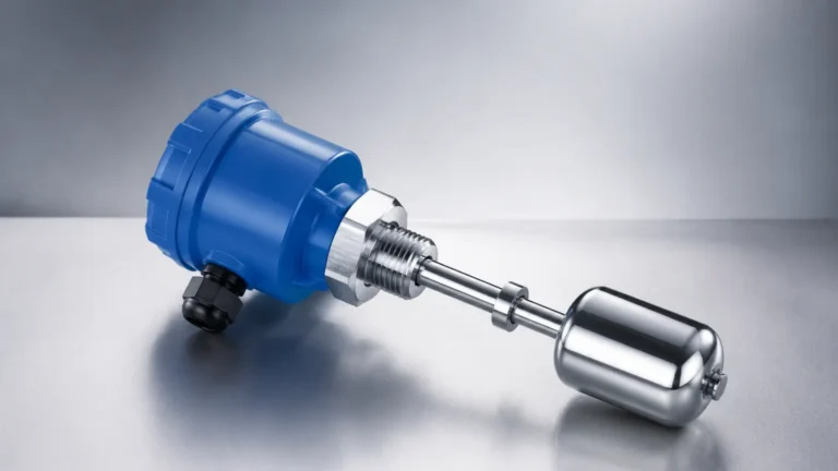
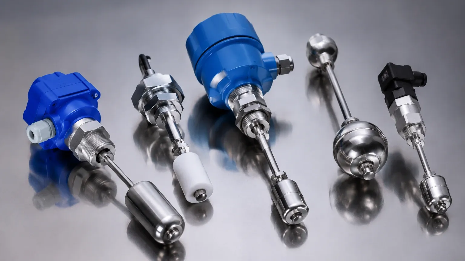
Float switches are among the most established technologies in the industry. They operate on Archimedes' principle: an object immersed in a fluid experiences an upward force equal to the weight of the fluid displaced. In a typical design, a float containing a magnet moves along a stem. When the liquid level rises, the float moves toward a reed switch embedded in the stem. The magnetic field closes (or opens) the circuit, triggering the alarm. These are highly effective for clean, non-coating liquids.
Vibrating Tuning Fork Switches (Frequency Shift)
This technology utilizes a sensing element shaped like a tuning fork, which is vibrated at its natural resonance frequency by piezoelectric crystals. When the fork is submerged in a liquid, the frequency of vibration drops due to the increased density of the surrounding medium. The internal electronics detect this frequency shift and convert it into a switching signal. Vibrating switches are versatile and largely unaffected by flow, turbulence, bubbles, or foam.
Conductive Level Switches (Electrical Resistance)
Conductive switches are used exclusively with conductive liquids, such as water, acids, or alkalis. The system consists of a low-voltage power source and one or more electrodes. When the liquid touches the electrode, it completes an electrical circuit between the probe and the tank wall (or a reference electrode). This change in resistance triggers the switch. These units are valued for their lack of moving parts and cost-effectiveness in wastewater applications.
Capacitive Level Switches (Dielectric Constant)
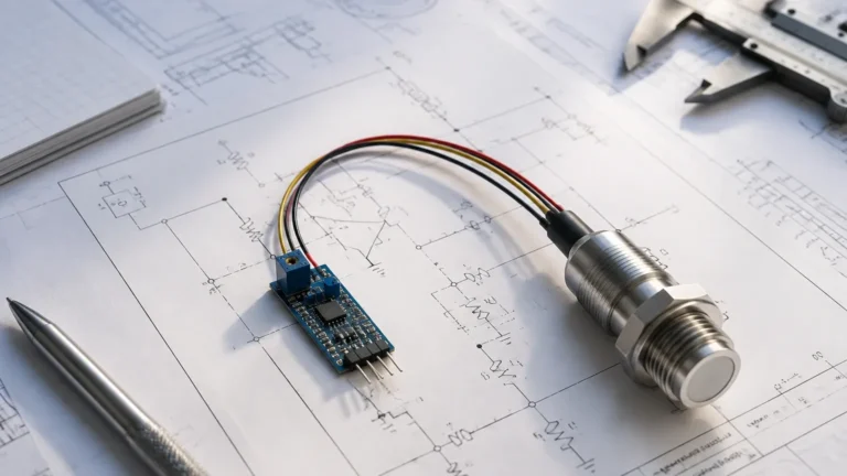
Capacitive sensors treat the probe and the tank wall as two plates of a capacitor. The liquid acts as a dielectric material. As the liquid level rises and covers the probe, the capacitance of the system changes because the dielectric constant of the liquid is significantly higher than that of air. This technology is robust but requires calibration to the specific dielectric constant of the media and may be sensitive to material buildup on the probe.
Ultrasonic and Optical Switches
Non-contact or gap-style ultrasonic switches use sound waves to detect the presence of liquid. In a gap-style sensor, a signal is transmitted across a small space; if liquid fills the gap, the signal is attenuated or transmitted differently, triggering the switch. Optical switches use an infrared LED and a phototransistor. When the sensor tip is in the air, the light is reflected back to the receiver. When submerged, the light is refracted into the liquid, breaking the circuit.
Technical Comparison and Selection Criteria
Choosing the right liquid level switches involves balancing technical performance with cost and maintenance requirements. The following table provides a comparison of common technologies based on typical industrial parameters.
| Technology | Media Type | Temp. Range (Typical) | Pressure Range (Typical) | Viscosity Handling | Coating Sensitivity |
| :— | :— | :— | :— | :— | :— |
| Float | Clean liquids | -40°C to 150°C | Up to 40 bar (580 psi) | Low | High |
| Tuning Fork | Most liquids/slurries | -50°C to 250°C | Up to 64 bar (928 psi) | High | Low/Medium |
| Conductive | Conductive only | -20°C to 100°C | Up to 10 bar (145 psi) | Medium | High |
| Capacitive | Most liquids | -40°C to 200°C | Up to 100 bar (1450 psi) | Medium | High (if not compensated) |
| Ultrasonic | Clean/Dirty liquids | -40°C to 90°C | Up to 20 bar (290 psi) | Low/Medium | Medium |
Key Evaluation Factors
1. Media Density and Viscosity: Float switches require a minimum density (specific gravity) to function correctly. Tuning forks are better suited for high-viscosity liquids or those containing solids.
2. Chemical Compatibility: The wetted parts (316L stainless steel, PTFE, PP, or PVC) must be resistant to the corrosive nature of the liquid.
3. Process Conditions: High-pressure or high-temperature environments often necessitate specialized tuning fork or capacitive designs rather than standard mechanical floats.
4. Output Requirements: Determine if the system requires a simple SPDT relay, a PNP/NPN transistor output, or a two-wire loop-powered signal.
Installation Best Practices for Industrial Environments
The reliability of liquid level switches is often determined by the quality of the installation. Even the most advanced sensor can fail if it is poorly positioned or incorrectly mounted.
Orientation and Positioning
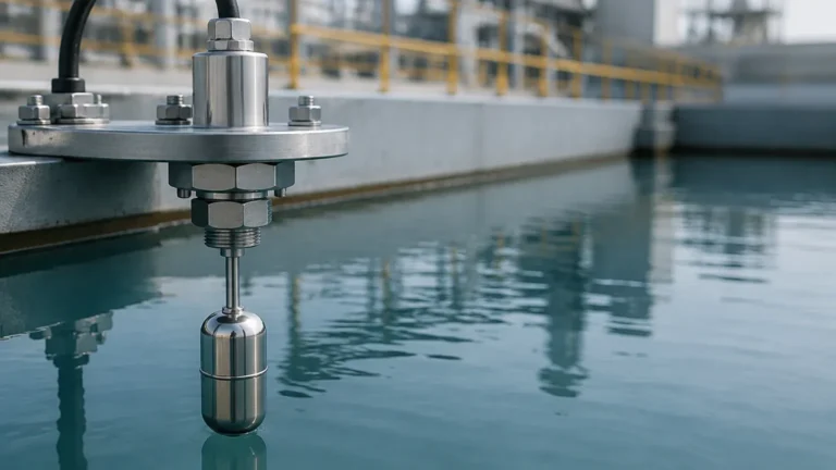
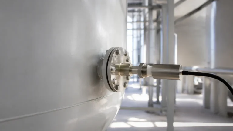
Switches can be mounted horizontally (through the side of the tank) or vertically (from the top). Vertical mounting is often preferred for high-level alarms to keep the electronics further from the liquid surface. For horizontal mounting, ensure the switch is positioned away from the direct path of the inlet flow to prevent false triggers caused by splashing or turbulence.
Avoiding Interference
* Agitators and Baffles: In tanks with mixers or agitators, the switch should be installed behind a baffle or in a stilling well to protect the sensing element from mechanical stress and surface agitation.
* Nozzle Length: For tuning fork and capacitive switches, the "dead zone" or the length of the mounting nozzle must be considered. If the nozzle is too long, material can become trapped, leading to a permanent "wet" signal even when the tank is empty.
* Proximity to Walls: Capacitive switches require a specific distance from the tank wall to maintain an accurate baseline capacitance reading.
Wiring and Sealing
Always use a drip loop in the cabling to prevent moisture from traveling down the wire and entering the housing. Ensure the cable glands are tightened to the manufacturer’s torque specifications to maintain the IP rating (typically IP65 to IP68) of the enclosure.
Operational Limitations and Common Application Risks
While liquid level switches are robust, engineers must be aware of potential failure modes to ensure long-term system integrity.
* Material Buoyancy and Coating: Float switches are susceptible to mechanical failure if the liquid is prone to crystallization or heavy scaling, which can "stick" the float in one position. In these cases, a non-mechanical vibrating fork or capacitive switch with coating compensation is a superior choice.
* Turbulence and Foam: Intense turbulence can cause mechanical fatigue in float stems or cause "chattering" in the relay output. Using a time-delay relay or a switch with built-in damping can mitigate this. Foam can also be problematic; some switches (like ultrasonic) might see the top of the foam as the liquid level, while others (like tuning forks) can be tuned to ignore foam and only trigger on the actual liquid.
* Dielectric Changes: For capacitive switches, if a process switches between different liquids with vastly different dielectric constants, the sensor may require recalibration to avoid false alarms.
* Electromagnetic Interference (EMI): In environments with large motors or variable frequency drives (VFDs), electronic switches must be properly shielded and grounded to prevent signal noise from triggering the relay.
Frequently Asked Questions (FAQs)
Q: Can liquid level switches be used for dry-run protection in pumps?
A: Yes, this is a primary application. A switch installed in the suction line or at the bottom of the supply tank can shut down the pump immediately if the liquid level drops below the minimum threshold, preventing damage to the pump seals and impellers.
Q: What is the difference between a "normally open" (NO) and "normally closed" (NC) switch?
A: This refers to the state of the electrical contact when the switch is in its "shelf" state (not triggered). For safety-critical applications like overfill prevention, a "fail-safe" configuration is usually used, where the circuit is closed during normal operation and opens when the alarm level is reached or if power is lost.
Q: How do I handle high-temperature liquids?
A: For temperatures exceeding 100°C (212°F), it is recommended to use switches with remote electronics or high-temperature extensions that move the sensitive electronic components away from the heat source. Welk offers specialized tuning fork models capable of operating up to 250°C (482°F).
Q: Are there switches suitable for hazardous areas?
A: Yes. For environments containing explosive gases or dust, you must specify intrinsically safe (Ex i) or explosion-proof (Ex d) versions of the switches. These are designed to prevent the electrical energy from the switch from igniting the surrounding atmosphere.
Summary of Selection and Maintenance
Liquid level switches are the unsung heroes of industrial safety and efficiency. By providing reliable point-level detection, they prevent environmental disasters, protect expensive machinery, and ensure process consistency. When selecting a switch, prioritize the physical characteristics of the media—viscosity, conductivity, and corrosiveness—over initial cost.
Regular maintenance should include a visual inspection of the sensing element for buildup and a functional "loop test" to ensure the relay correctly communicates with the PLC or control system. For complex applications involving aggressive chemicals or extreme pressures, consulting with a specialized manufacturer like Welk ensures that the selected Level Switches meet the specific demands of the project. By following rigorous installation standards and understanding the limitations of each technology, engineering teams can achieve high levels of reliability and safety in their liquid management systems.