Level Switch Electrode Type
Level Switch Electrode Type
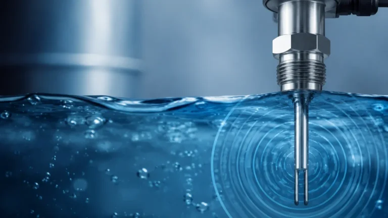
In the landscape of industrial automation, point level detection serves as a critical safeguard for process control, overflow prevention, and pump protection. Among the various technologies available, the conductive level switch remains a staple due to its simplicity, lack of moving parts, and high reliability. When engineers evaluate these systems, the specific level switch electrode type chosen often dictates the long-term success of the installation. This guide provides a detailed technical overview of electrode-based level measurement, covering principles, selection criteria, and practical application engineering.
Measurement Principles of Conductive Level Switches
Conductive level switches operate on the basic principle of electrical conductivity. The system typically consists of an electronic relay (the controller) and one or more electrodes (the sensors) inserted into the vessel.
The measurement circuit is completed when a conductive liquid reaches the tip of the electrode. A low-voltage AC signal—typically between 5V and 24V—is applied to the electrodes. Using Alternating Current (AC) is vital in these applications to prevent electrolysis and the subsequent corrosion or plating of the electrodes that would occur with a Direct Current (DC) signal.
When the liquid makes contact with the electrode, it creates a path of low resistance between the sensing electrode and a reference electrode (or the metal wall of the tank). This change in resistance is detected by the controller, which then triggers a relay output to signal a high or low level. Because this method relies on the liquid's ability to conduct electricity, it is exclusively used for conductive media such as water, acids, alkalis, and various aqueous solutions. It is not suitable for non-conductive liquids like oils, hydrocarbons, or pure distilled water.
Understanding Level Switch Electrode Type Variations
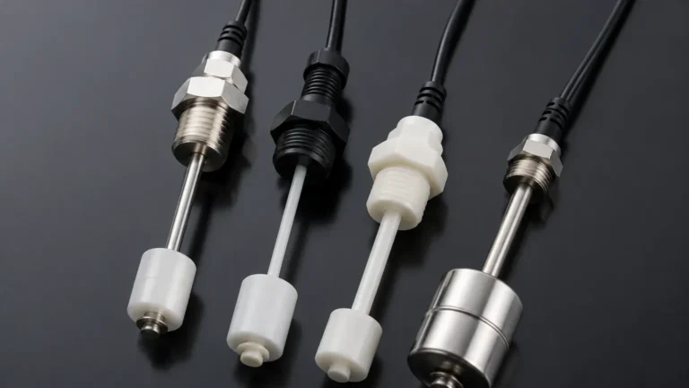
Selecting the appropriate level switch electrode type depends on the tank geometry, the depth of the measurement point, and the chemical nature of the liquid. Electrodes are generally categorized into three primary forms:
1. Rigid Rod Electrodes
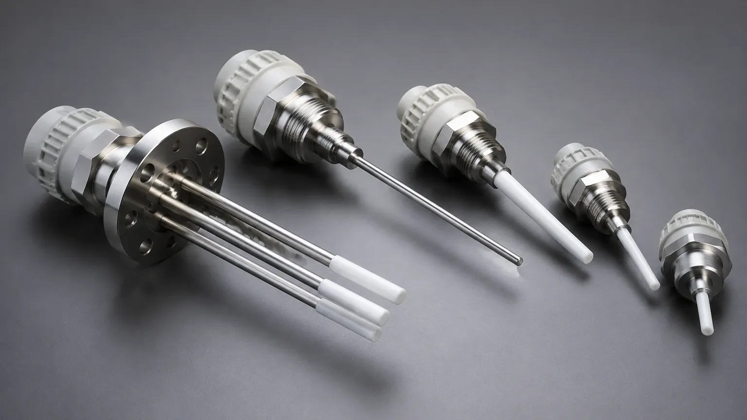
Rigid rods are the most common choice for shallow to medium-depth tanks, typically ranging from 100 mm to 3,000 mm (approx. 4 inches to 10 feet). These are usually manufactured from stainless steel and can be coated with insulating materials like PTFE or Polyolefin to prevent false triggering caused by splashing or foam.
2. Flexible Cable Electrodes
For deep wells, boreholes, or very tall storage silos, rigid rods become impractical due to shipping constraints and installation headroom. Cable electrodes utilize a weighted stainless steel probe suspended by a high-strength, insulated cable. These can extend up to 20 or 30 meters (65 to 100 feet). The weight ensures the cable remains vertical even in slightly turbulent conditions.
3. Multi-Point Electrode Heads
A single process connection can often house multiple electrodes of varying lengths. This allows a single Level Switches installation to manage several setpoints, such as "Pump Start," "Pump Stop," and "High-Level Alarm," significantly reducing the number of tank penetrations required.
Material Selection and Chemical Compatibility
The longevity of a level switch electrode type is directly tied to its material composition. Since the electrode is in direct contact with the process media, it must withstand chemical attack and temperature fluctuations.
* 304/316 Stainless Steel: The standard for water treatment, food and beverage, and general industrial applications. It offers excellent mechanical strength and moderate corrosion resistance.
* Hastelloy C / Titanium: Reserved for highly aggressive chemical environments, such as concentrated acids or seawater, where standard stainless steel would succumb to pitting or stress corrosion cracking.
* PTFE/PFA Coating: Used primarily for insulation. If the liquid is prone to leaving conductive residues or if there is heavy foam, a partial coating ensures that the circuit only completes at the very tip of the electrode, preventing "bridging" and false alarms.
Technical Selection Table
The following table provides a comparison to assist in selecting the correct level switch electrode type based on common process parameters.
| Feature | Rigid Rod Electrode | Flexible Cable Electrode | Multi-Point Assembly |
| :— | :— | :— | :— |
| Max Measurement Length | 3 meters (10 ft) | 30 meters (100 ft) | 3 meters (10 ft) |
| Typical Application | Process tanks, sumps | Deep wells, reservoirs | Pump control (Start/Stop) |
| Installation Space | Requires vertical clearance | Minimal clearance needed | Single process entry |
| Media Type | Conductive liquids | Conductive liquids | Conductive liquids |
| Pressure Rating | Up to 40 bar (580 psi) | Usually atmospheric | Up to 20 bar (290 psi) |
| Maintenance | Low | Low (check cable tension) | Low |
Installation Considerations and Best Practices
Proper installation is paramount to ensuring the accuracy of the electrode system. Engineers should adhere to the following guidelines:
1. Reference Grounding: In metal tanks, the tank wall can serve as the ground (reference) electrode. However, in plastic or fiberglass (FRP) tanks, a dedicated "reference electrode" must be installed. This electrode should be the longest in the assembly, reaching below the lowest switching point.
2. Avoid Turbulence: Electrodes should not be installed directly in the path of a tank's inlet flow. Excessive turbulence can cause the rods to sway, leading to mechanical fatigue or intermittent signals. If turbulence is unavoidable, the use of a stilling well is recommended.
3. Electrode Spacing: When using multiple bare rods, ensure they are spaced at least 10 mm to 20 mm (0.4 to 0.8 inches) apart to prevent accidental contact. In applications with high vibration, spacers (insulators) should be installed every 1 meter (3.3 feet) to maintain separation.
4. Sensitivity Adjustment: Most modern controllers allow for sensitivity adjustment (measured in Ohms). For liquids with low conductivity, such as condensate, the sensitivity must be increased. For highly conductive liquids like salt water, sensitivity should be lowered to prevent false trips from moisture or steam.
Limitations and Environmental Constraints
While the level switch electrode type is highly versatile, it is not a universal solution. Understanding its limitations prevents costly engineering errors:
* Conductivity Requirement: The liquid must have a minimum conductivity, typically >5 μS/cm. This excludes most oils, fuels, and ultra-pure water used in semiconductor manufacturing.
* Coating and Buildup: If the process liquid is prone to crystallization or leaves a thick, conductive film (like some wastewater sludges), the electrodes may "short out" even when the liquid level has dropped. In these cases, ultrasonic or tuning fork switches may be more appropriate.
* Vessel Material: As mentioned, non-conductive vessels require an extra electrode for the return path, which increases the complexity of the sensor head.
Frequently Asked Questions (FAQs)
Q: Can I cut the electrodes to length on-site?
A: Yes, most rigid rod level switch electrode types are designed to be cut to the desired length during installation. Ensure that any insulation (like PTFE) is stripped back at the tip (approx. 10-20 mm) to allow for electrical contact.
Q: Why is my level switch staying "On" even after the tank is empty?
A: This is usually caused by "bridging." Conductive residue or moisture may be creating a path between two electrodes or between an electrode and the tank wall. Cleaning the electrodes or using a model with a protective sleeve/coating can resolve this.
Q: Is there a maximum distance between the electrode and the controller?
A: Yes. Because the system relies on measuring resistance, excessively long cable runs between the tank and the control room can introduce enough capacitance or resistance to interfere with the signal. Generally, distances up to 100 meters (330 feet) are acceptable, but shielded cable is recommended for runs over 30 meters (100 feet).
Q: Can these be used in high-temperature steam applications?
A: Conductive switches can be used in boiler level control, but they require specialized high-pressure, high-temperature ceramic insulators. Standard plastic-housed electrodes are typically limited to 100°C (212°F).
Conclusion
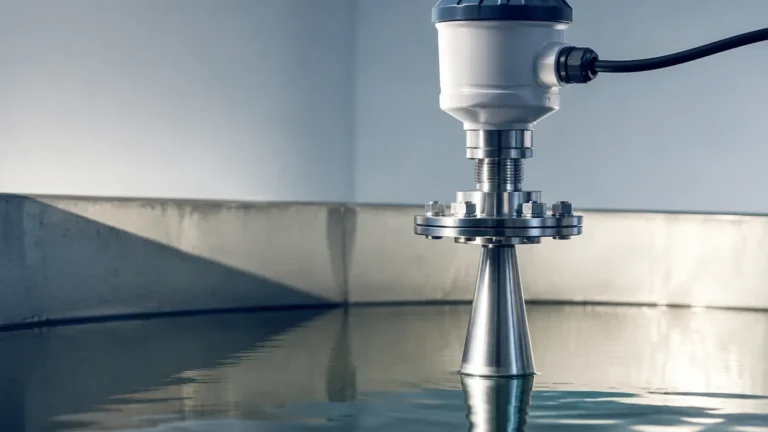
The level switch electrode type remains a cornerstone of industrial liquid management due to its cost-effectiveness and straightforward operation. By matching the electrode material and form factor (rod vs. cable) to the specific chemical and physical properties of the media, facilities can achieve reliable point level detection with minimal maintenance. For complex applications involving non-conductive liquids or heavy buildup, engineers should consult with a technical specialist to explore alternative technologies such as radar or ultrasonic sensors.