Magnetic Float Level Switches
Magnetic Float Level Switches
In the landscape of industrial automation and process control, the ability to detect specific liquid levels with high reliability is fundamental. Magnetic float level switches represent one of the most established and widely utilized technologies for point-level detection. These devices are engineered to provide a discrete output—typically a dry contact—when a liquid reaches a predetermined height within a tank or vessel.
As a professional manufacturer, Welk specializes in providing robust level measurement instruments designed for demanding environments. Understanding the mechanical and electrical nuances of magnetic float level switches is essential for engineers and plant operators to ensure system safety, prevent tank overfills, and manage pump automation effectively.
Understanding the Measurement Principle of Magnetic Float Level Switches
The operation of magnetic float level switches is based on two primary physical principles: buoyancy and magnetism. Unlike continuous level sensors that provide a constant 4-20mA or digital signal representing the exact level, these switches are designed for "point-level" detection, triggering an action at a specific threshold.
The Buoyancy Component
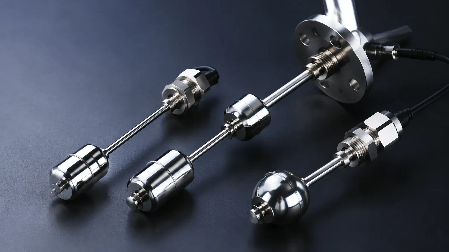
The device consists of a hollow float that contains an internal permanent magnet. This float is designed with a specific density lower than that of the process liquid. As the liquid level rises or falls, the float moves vertically along a stationary stem or guide tube.
The Magnetic Interaction
Inside the hermetically sealed stem are one or more reed switches. These reed switches consist of two overlapping, ferromagnetic blades (reeds) sealed within a glass envelope. When the float’s internal magnet moves into the proximity of the reed switch, the magnetic field pulls the blades together, completing an electrical circuit. Conversely, when the float moves away, the blades return to their original state due to their inherent spring tension.
Because the reed switches are completely isolated from the process media inside the sealed stem, they are protected from corrosion, oxidation, and humidity. This isolation is a key factor in the long service life of magnetic float level switches in chemical and water treatment applications.
Types and Configurations
Magnetic float level switches are highly versatile and can be configured in several ways to suit different tank geometries and application requirements.
Single-Point vs. Multi-Point Switches
* Single-Point Switches: These are used for basic high-level or low-level alarms. They feature one float and one reed switch. They are common in small sumps or as redundant safety overflows.
* Multi-Point Switches: A single stem can house multiple reed switches at different heights (e.g., 500 mm, 1000 mm, and 1500 mm). A single float can trigger multiple switches, or multiple floats can be used on one stem to track different levels. This is ideal for controlling a pump (start/stop) and providing a high-level alarm using a single process connection.
Mounting Orientations
* Top-Mounted: The stem is inserted through the top of the tank. This is the most common configuration for deep tanks or underground sumps.
* Side-Mounted: These switches often use a hinged float or a horizontal displacement mechanism. They are used when top access is restricted or when only a single point near a specific side-wall location needs monitoring.
Technical Selection Criteria for Industrial Applications
Selecting the correct Level Switches requires a detailed analysis of the process media and the environmental conditions. Failure to account for these factors can lead to premature mechanical failure or inaccurate switching.
1. Liquid Specific Gravity (SG)
The buoyancy of the float depends on the density of the liquid. A float designed for water (SG 1.0) may not float in a light hydrocarbon or alcohol with an SG of 0.6. Engineers must specify the minimum specific gravity of the liquid to ensure the float provides enough buoyant force to move the magnet past the switch point.
2. Material Compatibility
* Stainless Steel (304 or 316L): Ideal for high-pressure (up to 40 bar / 580 psi) and high-temperature (up to 200°C / 392°F) applications. It is widely used in the oil and gas industry and for food-grade applications.
* Plastic (PP, PVC, PVDF): Polypropylene (PP) is cost-effective for water and general chemicals. PVDF is reserved for highly aggressive acids or high-purity deionized water where metal contamination must be avoided.
3. Temperature and Pressure
Standard plastic switches are often limited to 80°C (176°F) and low pressures. For boiler feed water or pressurized chemical reactors, stainless steel variants are necessary. It is important to note that as temperature increases, the maximum allowable pressure for the float typically decreases.
4. Electrical Load
Reed switches have specific contact ratings (e.g., 50W, 0.5A). They are generally intended for signaling a PLC (Programmable Logic Controller) or a high-impedance relay. Directly switching a high-power pump motor through a reed switch will cause the contacts to weld together instantly. Always use an interposing relay for inductive or high-current loads.
Selection Table: Magnetic Float vs. Alternative Technologies
When evaluating magnetic float level switches, it is helpful to compare them against other common point-level technologies to determine the best fit for the project.
| Feature | Magnetic Float Switch | Tuning Fork (Vibrating) | Ultrasonic Switch | Optical Switch |
| :— | :— | :— | :— | :— |
| Measurement Principle | Buoyancy/Magnetic | Vibration Damping | Sound Reflection | Light Refraction |
| Moving Parts | Yes | No | No | No |
| Viscous Liquids | Poor | Good | Fair | Poor |
| Foam Sensitivity | Low | Moderate | High | High |
| Cost | Low to Moderate | Moderate | High | Moderate |
| Typical Accuracy | ±2 mm to ±5 mm | ±1 mm | ±2 mm | ±1 mm |
| Max Temperature | Up to 200°C | Up to 150°C | Up to 90°C | Up to 125°C |
Installation and Mounting Guidelines
To ensure the long-term reliability of magnetic float level switches, follow these engineering best practices during installation:
1. Avoid Magnetic Interference: Do not install the switch near strong electromagnetic fields, such as large motors, transformers, or high-voltage cables. Additionally, ensure the tank wall is not made of a ferromagnetic material that could interfere with the float’s magnetic field (though most industrial tanks are 316SS or plastic).
2. Stilling Wells for Turbulence: In tanks with heavy agitation or splashing, the float may bounce, causing "chatter" in the electrical signal. Installing the switch inside a stilling well (a pipe with vent holes) protects the float from mechanical turbulence and ensures a stable switching point.
3. Vertical Alignment: Top-mounted switches must be installed within 30 degrees of vertical. Excessive tilting can cause the float to bind against the stem, preventing it from rising or falling with the liquid.
4. Clearance: Ensure there is sufficient clearance between the float and the tank wall or internal structures (like ladders or heating coils) to prevent the float from getting stuck.
Operational Limitations and Maintenance
While magnetic float level switches are highly reliable, they are not suitable for every environment. Awareness of these limitations is critical for process safety.
* Build-up and Scaling: In liquids that tend to crystallize or leave heavy deposits (like lime slurry or crude oil), the float may eventually stick to the stem. Regular inspection and cleaning are required in these applications.
* Magnetic Particles: If the process liquid contains iron filings or magnetic scales, these particles will be attracted to the float's magnet. Over time, this accumulation can change the float's buoyancy or jam the mechanism.
* Viscosity: Highly viscous liquids (above 100 cp) can slow down the movement of the float, leading to a delayed response time. For very thick oils or resins, non-contact or vibrating technologies are usually preferred.
Maintenance Checklist
* Quarterly: Perform a manual "bucket test" or lift the float manually to ensure the electrical contact triggers the expected alarm or pump action.
* Bi-Annually: Inspect the float for signs of pitting, corrosion, or deformation (collapsing due to over-pressure).
* Annually: Check the wiring integrity and ensure that moisture has not entered the junction box through the conduit.
Frequently Asked Questions (FAQ)
Q: Can I change a magnetic float switch from Normally Open (NO) to Normally Closed (NC)?
A: In many designs, yes. This is often achieved by removing the retaining clip at the end of the stem, sliding the float off, flipping it 180 degrees, and reinstalling it. The internal magnet position changes relative to the reed switch, reversing the logic.
Q: What is the maximum length for a vertical float switch stem?
A: Welk can manufacture stems up to 4 meters (approx. 13 feet) or more, but very long stems require support brackets to prevent swaying and potential bending due to fluid movement.
Q: Are these switches suitable for hazardous areas (Ex-proof)?
A: Yes, magnetic float switches can be used in hazardous areas if they are paired with an intrinsically safe (IS) barrier or if the switch housing is rated as explosion-proof (NEMA 7/9 or ATEX/IECEx d). Because the reed switch is a "simple apparatus," it is easily integrated into IS circuits.
Q: How do I handle liquids with varying densities?
A: If the density varies significantly, you must select a float that is buoyant at the *lowest* expected specific gravity. If the float is too heavy for the lightest liquid, it will sink and fail to trigger the high-level alarm.
Conclusion
Magnetic float level switches remain a cornerstone of industrial level control due to their simplicity, lack of power requirement (for the sensing element itself), and cost-effectiveness. By carefully matching the material, specific gravity, and mounting configuration to the application, users can achieve highly dependable point-level detection.
For complex chemical processes or high-pressure steam applications, consulting with a specialized manufacturer like Welk ensures that the instrument is tailored to the specific rigors of the environment. Whether you require a simple single-point plastic switch for a water tank or a multi-point stainless steel assembly for an oil separator, selecting the right technology is the first step toward operational excellence.