How Do Float Level Switches Work
How Do Float Level Switches Work
In the realm of industrial automation and process control, ensuring that liquid levels remain within safe and operational limits is critical. Among the various technologies available for this task, the float level switch remains one of the most reliable, cost-effective, and widely implemented solutions. Whether used for high-level alarm protection, low-level pump control, or leak detection, understanding the underlying mechanics and selection criteria is essential for any plant engineer or system integrator.
This guide explores the fundamental principles of how float level switches work, their various configurations, and the practical considerations necessary for successful deployment in industrial environments.
The Core Principle: Buoyancy and Magnetic Coupling
To answer the question, "how do float level switches work?" one must first look at Archimedes' principle of buoyancy. This principle states that any object, wholly or partially immersed in a fluid, is buoyed up by a force equal to the weight of the fluid displaced by the object.
In a float level switch, a float—typically a hollow sphere or cylinder—is designed with a lower density than the liquid it is intended to measure. As the liquid level rises, the float rises with it. The "switching" action occurs when the float reaches a predetermined point, triggering an electrical contact.
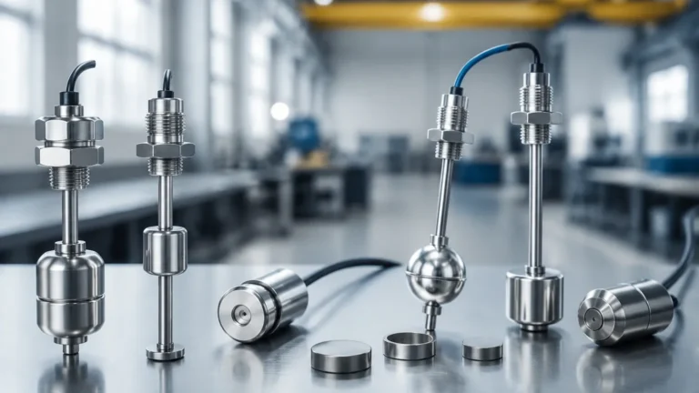
Most modern industrial float switches utilize magnetic coupling rather than direct mechanical linkages. This design provides a hermetic seal between the process fluid and the electrical components, significantly increasing the lifespan and safety of the device. Inside the float is a permanent magnet. As the float moves along a stem or pivots on an arm, its magnetic field interacts with a stationary reed switch or a microswitch located outside the wetted area.
The Role of the Reed Switch
A reed switch consists of two overlapping, ferromagnetic blades (reeds) sealed within a glass tube. When the magnet in the float comes into proximity, the magnetic field pulls the reeds together (for a Normally Open configuration) or pushes them apart (for a Normally Closed configuration). Because these contacts are sealed in an inert gas environment, they are protected from oxidation and corrosion, making them ideal for long-term industrial use.
Common Types of Float Level Switches
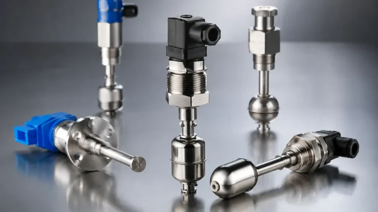
While the basic principle of buoyancy is universal, the mechanical execution varies based on the application requirements. Level Switches are generally categorized into three main designs:
1. Vertical Float Switches
Vertical switches consist of a central stem with one or more floats that slide up and down. The stem contains the reed switches at specific heights.
- Operation: As the liquid rises, the float slides up the stem. When the internal magnet aligns with the reed switch inside the stem, the circuit closes or opens.
- Advantage: They are compact and can support multiple switching points on a single stem (e.g., high-high, high, low, and low-low levels).
2. Side-Mounted (Horizontal) Float Switches
These are installed through the side wall of a tank. They often use a hinged arm or a pivoting mechanism.
- Operation: As the liquid level passes the installation point, the float pivots upward. This movement either moves a magnet toward a reed switch in the mounting housing or mechanically trips a microswitch.
- Advantage: Ideal for tanks where top access is restricted or for very deep tanks where a long vertical stem would be impractical.
3. Cable-Suspended (Tilt) Float Switches
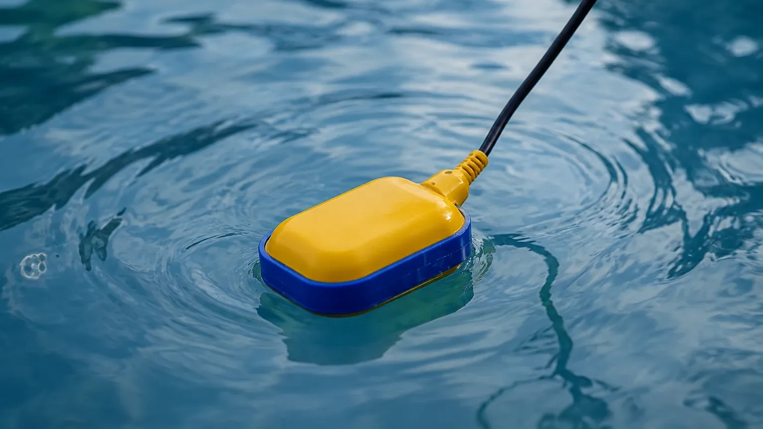
Often used in water treatment and sewage applications, these consist of a large float attached to a flexible cable.
- Operation: The float hangs vertically when the liquid is low. As the level rises, the float eventually tips over (tilts). This change in orientation causes an internal ball or weight to move, triggering a mechanical switch.
- Advantage: Highly robust and resistant to turbulence and debris, making them suitable for non-potable water and wastewater.
Material Selection and Fluid Compatibility
Selecting the right material for the float and stem is critical to ensure the longevity of the instrument. The material must withstand the chemical nature of the fluid, the operating temperature, and the system pressure.
| Material | Typical Applications | Temperature Range | Pressure Rating |
| :— | :— | :— | :— |
| 316L Stainless Steel | Food & beverage, oil, high-temp chemicals | -40°C to +200°C | Up to 40 bar |
| Polypropylene (PP) | Water, general acids, and bases | -10°C to +80°C | Atmospheric |
| PVDF / PTFE | Highly corrosive acids, aggressive solvents | -20°C to +120°C | Moderate |
| Buna-N (Nitrile) | Oils, fuels, and petroleum products | -20°C to +100°C | Up to 10 bar |
Technical Selection Criteria
When specifying a float level switch for a project, engineers should evaluate the following technical parameters:
1. Specific Gravity (Density): The float must be lighter than the liquid. Most standard floats are designed for liquids with a specific gravity of 0.8 or higher. If the liquid is very light (e.g., certain hydrocarbons), a specialized high-buoyancy float is required.
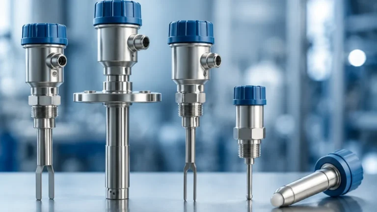
2. Viscosity: Highly viscous liquids can cause "drag" on the float, leading to delayed switching or sticking. If the liquid is prone to crystallization or coating, non-contact methods like radar or ultrasonic sensors might be preferred, though large-diameter floats can sometimes mitigate these issues.
3. Switching Logic: Determine if you need Normally Open (NO) or Normally Closed (NC) contacts. Many vertical float switches allow the user to reverse the logic simply by removing the float and flipping it 180 degrees.
4. Electrical Load: Reed switches are excellent for signaling PLCs or triggering low-power relays. However, if you are directly switching a pump motor, a heavy-duty microswitch or an external contactor is mandatory to prevent welding the contacts.
Installation Considerations
Correct installation is the difference between a reliable system and frequent downtime. Follow these engineering guidelines:
* Avoid Turbulence: Do not install a float switch directly under a fill pipe or near an agitator. The resulting turbulence can cause "chatter" (rapid cycling of the switch), which can damage pumps and burn out the switch contacts. If turbulence is unavoidable, use a stilling well (a perforated pipe that surrounds the float to dampen wave action).
* Vertical Alignment: For stem-type switches, ensure the unit is mounted within 30 degrees of vertical. Excessive tilting can increase friction between the float and the stem, leading to sticking.
* Dead Zones: Be aware of the "dead zone" at the top and bottom of the stem. The float requires a certain amount of travel distance before the magnet aligns with the internal switch. Ensure your tank's operational levels account for these physical dimensions.
* Wiring and Protection: Use appropriate cable glands to maintain the IP rating of the housing. In hazardous environments (oil & gas, chemical processing), ensure the switch is used with an intrinsically safe barrier or is housed in an explosion-proof enclosure.
Limitations and Common Risks
While float level switches are versatile, they are not universal solutions. Engineers should be aware of the following limitations:
* Mechanical Wear: Because they are moving parts, they are subject to mechanical wear over millions of cycles. Regular inspection is recommended in critical safety applications.
* Build-up and Scaling: In applications like wastewater or lime slurry, solids can build up on the stem or float. This increases the weight of the float or causes it to jam. In these cases, periodic cleaning is required.
* Ferrous Particles: If the process liquid contains iron filings or magnetic particles, they will be attracted to the float's internal magnet. This can lead to jamming or false triggering. A magnetic trap or a non-magnetic level technology should be used instead.
Frequently Asked Questions (FAQs)
Q: Can a float level switch be used for continuous level measurement?
A: Standard float switches are for point-level detection (on/off). However, "float level transmitters" exist which use a series of reed switches and resistors (or a magnetostrictive wire) to provide a continuous 4-20mA signal.
Q: What causes a float switch to fail?
A: The most common causes are contact welding due to electrical overcurrent, float puncture (causing it to sink), or mechanical jamming due to debris or scale build-up.
Q: How do I test a float level switch?
A: With the power disconnected, use a multimeter set to resistance (Ohms). Manually move the float up and down. You should see the resistance move from infinity (Open) to near zero (Closed).
Q: Can I use a water float switch for oil?
A: It depends on the density. Oil is less dense than water. A float designed strictly for water (SG 1.0) might not be buoyant enough to float in light oil (SG 0.7). Always check the specific gravity rating of the switch.
Conclusion
Understanding how float level switches work is fundamental to designing reliable liquid management systems. By leveraging the simple yet effective power of buoyancy and magnetic switching, these devices provide clear, unambiguous signals for process control. When selected with the correct materials and installed with attention to the physical dynamics of the tank, a float switch can provide years of maintenance-free service. For complex applications or specialized chemical environments, consulting with a professional manufacturer like Welk ensures that the chosen Level Switches meet the necessary safety and performance standards of modern industry.