Level Sensor 3d
Level Sensor 3d
In the landscape of industrial automation, the transition from simple point detection to comprehensive volumetric mapping has revolutionized how bulk solids and liquids are managed. While traditional sensors provide a single point of data, a level sensor 3d offers a sophisticated spatial representation of the material surface. This technology is particularly critical in silos, bunkers, and warehouses where material distribution is rarely uniform. Understanding the engineering principles, selection criteria, and the relationship between these advanced scanners and fundamental Level Switches is essential for optimizing inventory accuracy and process safety.
The Evolution of Industrial Level Measurement
For decades, process engineers relied on one-dimensional measurements. A single radar or ultrasonic beam would measure the distance to the material directly beneath the sensor. However, in bulk solids—such as grain, cement, or coal—the material often forms cones, craters, or "rat-holes." A single-point measurement can lead to significant errors in volume calculation, sometimes exceeding 15% to 20% of the actual inventory.
A level sensor 3d addresses this by scanning multiple points across the surface area. By integrating these data points into a digital map, the system calculates the actual volume rather than just the height at a specific coordinate. This capability is the cornerstone of modern inventory management, allowing for tighter supply chain control and reduced safety stock requirements.
How a Level Sensor 3d Works: Measurement Principles
Most 3D level measurement systems utilize acoustic or radar technology to generate a three-dimensional map. The two primary methods are acoustic phased-array scanning and multi-point radar mapping.
Acoustic Scanners
These devices use three or more transducers to emit low-frequency acoustic pulses (typically between 3 kHz and 10 kHz). By measuring the time-of-flight of the echoes and the phase difference between the transducers, the sensor can determine the direction and distance of multiple points on the material surface.
The low frequency allows the pulses to penetrate heavy dust, which is common during the filling of silos. The device then uses complex algorithms to process these "clouds" of data points into a volumetric value and a visual 3D representation of the material topography.
Radar-Based 3D Mapping
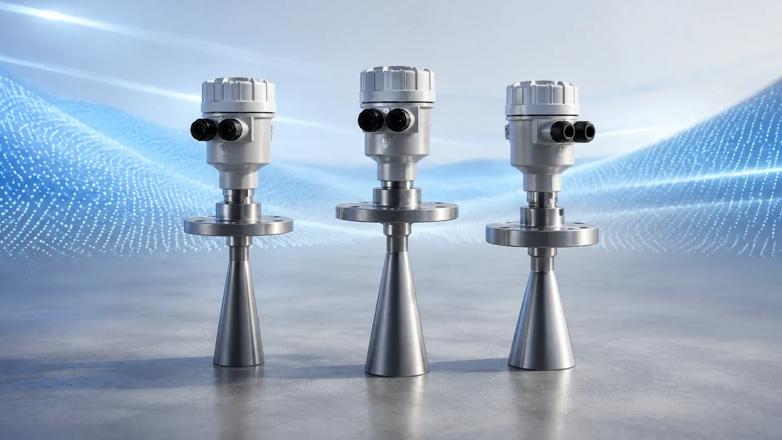
Advanced radar systems use high-frequency signals (often in the 76-81 GHz range) with a narrow beamwidth. Some high-end systems employ a rotating antenna or an array of antennas to scan the surface. Radar technology is generally preferred in high-temperature or high-pressure environments where acoustic signals may be attenuated by the atmosphere within the vessel.
Comparing 3D Mapping with Traditional Level Switches
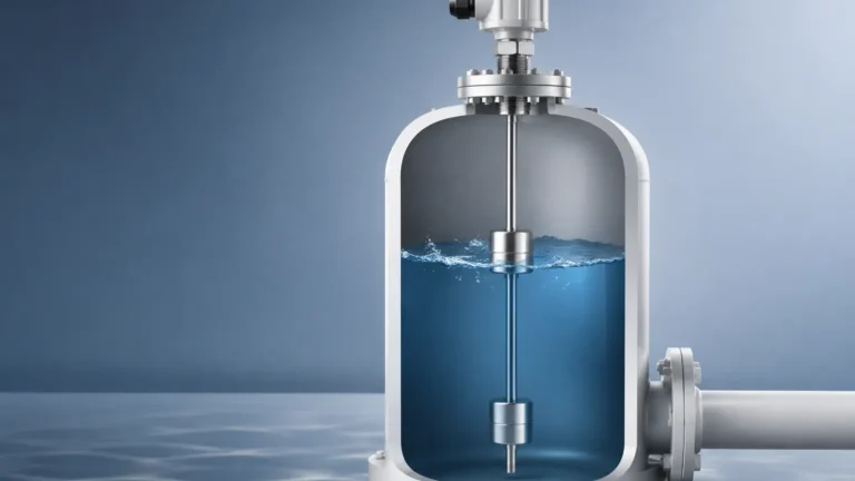
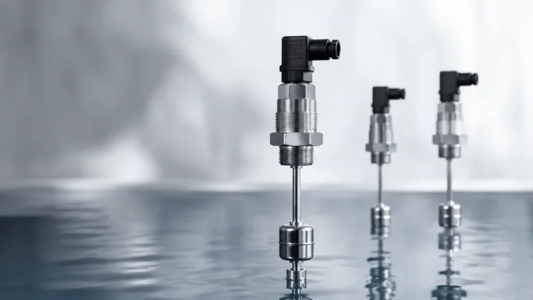
It is a common misconception that the adoption of a level sensor 3d eliminates the need for basic level detection. In a robust engineering design, these technologies serve complementary roles. While the 3D sensor provides continuous data for inventory and process optimization, Level Switches provide the necessary redundancy for overfill protection and dry-run prevention.
| Feature | Level Sensor 3d | Level Switches |
| :— | :— | :— |
| Primary Function | Volumetric inventory and mapping | Point detection for safety/control |
| Data Output | Continuous 4-20mA, Modbus, or Ethernet | Discrete Relay or Transistor output |
| Accuracy | High volumetric accuracy (typically <3%) | Precision at a specific point |
| Redundancy | Usually the primary measurement | Secondary safety layer (SIL rated) |
| Cost | Higher initial investment | Cost-effective and reliable |
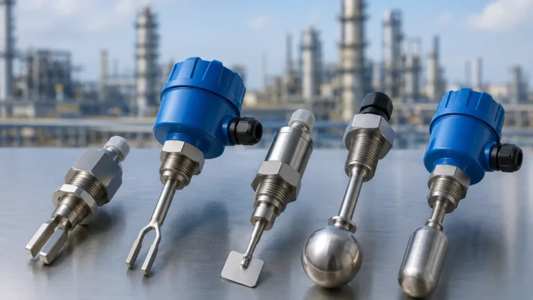
In a typical grain silo, a 3D scanner might be used to track the total tonnage of corn, while a vibrating fork or rotary paddle switch is installed at the very top of the silo to trigger an emergency shutdown of the conveyor belt if the material reaches a critical height, regardless of what the scanner reports.
Key Selection Criteria for 3D Level Scanners
When specifying a level sensor 3d, engineers must evaluate several environmental and process variables to ensure reliable performance.
1. Vessel Dimensions and Geometry
The range of the sensor is a primary constraint. Most acoustic 3D scanners can measure up to 30 meters (approximately 98 feet) or more, but the width of the vessel also matters. In very wide silos (e.g., 15 meters or 50 feet in diameter), multiple sensors may be required to cover the entire surface area and eliminate "blind spots" created by internal structural beams.
2. Material Characteristics
The dielectric constant, bulk density, and angle of repose of the material influence how signals reflect. Materials with a low dielectric constant (like plastic pellets) may require more sensitive radar systems. For acoustic sensors, the "softness" of the material (like fine powder) can absorb sound waves, requiring a lower-frequency transducer to ensure a strong return signal.
3. Dust and Vapor Conditions
If the application involves heavy dust during filling (e.g., flour or cement), acoustic scanners are often superior because low-frequency sound waves are less affected by suspended particulates than high-frequency light or radar waves. Conversely, if the vessel contains heavy vapors or gases that change the speed of sound, a radar-based system is more stable.
4. Temperature and Pressure
Standard 3D sensors are typically rated for temperatures up to 70°C (158°F). For high-heat applications like clinker silos or fly ash hoppers, specialized cooling jackets or high-temperature transducer materials are necessary. Pressure ratings must also be checked if the vessel is pressurized or under vacuum.
Installation and Mounting Considerations
The performance of a level sensor 3d is heavily dependent on its physical placement. Unlike a point level switch, which is often mounted on the side wall, a 3D scanner must be mounted on the roof of the vessel with a clear line of sight to the material surface.
* Avoid the Filling Stream: The sensor should never be placed directly under the inlet. The falling material will create "noise" in the data and may cause physical wear on the sensor face.
* Internal Obstructions: Manways, ladders, and cross-braces can create false echoes. While modern software can "map out" these fixed obstructions, it is best to place the sensor where it has the clearest view of the material.
* Nozzle Design: If the sensor is mounted on a nozzle, the nozzle must be as short and wide as possible to prevent the signal from reflecting off the nozzle walls before it even enters the tank.
Limitations and Maintenance
While highly capable, 3D level sensors are not "set and forget" devices. They have specific limitations that must be managed:
* Processing Power: The calculation of a 3D map requires significant computational power. There is often a slight delay (seconds to minutes) between the scan and the updated volume reading, making them less suitable for high-speed batching processes compared to Level Switches.
* Surface Buildup: In sticky applications, material can accumulate on the sensor face. Some 3D scanners include a self-cleaning function or a port for compressed air to blow off dust.
* Calibration Complexity: Initial setup requires accurate vessel dimensions (height, diameter, cone angle). If the vessel geometry is entered incorrectly, the volumetric calculation will be systematically flawed.
Practical Selection Table
Use the following table as a general guide for selecting the appropriate technology based on the application type.
| Application | Recommended Technology | Reason |
| :— | :— | :— |
| Large Grain Silo | Acoustic level sensor 3d | Handles dust well; maps irregular cones. |
| Liquid Chemical Tank | 80GHz Radar or Ultrasonic | Smooth surface doesn't require 3D mapping. |
| Cement Storage | Acoustic 3D Scanner | Penetrates extreme dust during pneumatic filling. |
| Small Plastic Hopper | Level Switches | Simple high/low control is sufficient. |
| Coal Bunker | Multi-point Radar or Acoustic | Large area requires volumetric data for inventory. |
Frequently Asked Questions
Can a 3D level sensor see through dust?
Acoustic-based 3D scanners are specifically designed to operate in dusty environments. The low-frequency sound waves have long wavelengths that can pass through suspended dust particles without significant scattering. Radar-based 3D sensors also perform well in dust, though extremely dense dust clouds may attenuate very high-frequency radar signals.
How many points does a 3D sensor measure?
This varies by manufacturer and technology. Some acoustic scanners measure between 10 and 50 discrete points to create a map, while high-resolution radar arrays can generate hundreds of data points. For most industrial inventory purposes, 15 to 30 points are sufficient to achieve a volumetric accuracy of 1% to 3%.
Is a 3D sensor better than a standard radar sensor?
It depends on the goal. If you only need to know the level of a liquid (which is always flat), a standard 1D radar is more cost-effective and faster. If you are managing solids that form hills and valleys, a level sensor 3d is significantly better because it accounts for the volume of material that a 1D sensor would ignore.
Does it require special software?
Yes, most 3D sensors come with proprietary software that visualizes the material surface. This software typically integrates with a PLC or SCADA system via Modbus RTU, HART, or Profibus to provide the calculated volume and mass data to the plant operators.
Conclusion
Implementing a level sensor 3d represents a significant step forward in process transparency. By providing a real-time visual and mathematical model of material storage, these sensors allow for optimized logistics and reduced waste. However, they should be viewed as one part of a comprehensive measurement strategy that includes reliable Level Switches for safety and point-level control. When selected and installed correctly, 3D mapping technology provides the data-driven foundation necessary for modern industrial automation.