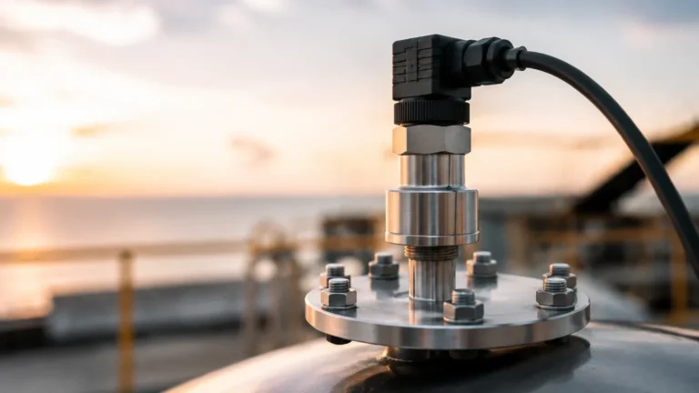
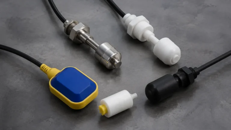
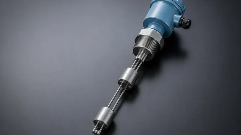
Level Sensor 3d Model
Level Sensor 3d Model
In modern industrial engineering, the design of process vessels, storage tanks, and piping systems has transitioned almost entirely into the digital realm. The use of a level sensor 3d model is no longer a luxury but a fundamental requirement for Mechanical and Piping Engineers. These digital representations allow for precise spatial coordination, ensuring that level measurement instruments—ranging from continuous transmitters to Level Switches—fit perfectly within the physical constraints of a plant’s infrastructure.
Integrating accurate 3D CAD data into a project’s Digital Twin or Building Information Modeling (BIM) workflow minimizes the risk of physical interference, optimizes maintenance access, and ensures that the sensor’s sensing element is positioned correctly relative to the process media. This guide explores the technical principles of level measurement, the role of 3D modeling in instrument selection, and the practical considerations for implementing these sensors in industrial environments.
Core Principles of Level Measurement
Before selecting a level sensor 3D model for a CAD assembly, it is essential to understand the underlying measurement technology. The physical form factor of the device is dictated by its operating principle, which in turn influences how it must be oriented and mounted.
Radar Level Measurement (ToF)
Radar level meters utilize Time-of-Flight (ToF) technology. High-frequency microwave pulses (typically 26 GHz or 80 GHz) are emitted by the antenna, reflected by the product surface, and received by the electronic evaluation system. The distance is proportional to the time it takes for the pulse to travel. In a 3D model, the antenna geometry—whether horn, lens, or rod—must be accurately represented to ensure the signal beam does not hit internal tank obstructions like agitators or heating coils.
Ultrasonic Level Sensors
Similar to radar, ultrasonic sensors use sound waves. A transducer emits an ultrasonic pulse that bounces off the liquid or solid surface. These are non-contact and cost-effective but require a clear path. The 3D model must account for the "blocking distance" or "dead zone" (typically 0.2m to 0.5m), where measurement is impossible due to the transducer's mechanical damping.
Hydrostatic Level Transmitters
Hydrostatic sensors measure the pressure exerted by a liquid column. The pressure is directly proportional to the height of the liquid based on its density. These are contact-based sensors. The 3D model is critical here for determining the exact tapping point or flange height on the vessel, as even a few millimeters of deviation can lead to zero-point errors in the final calibration.
Magnetic Level Gauges and Switches
Magnetic level gauges use a float containing a magnet that travels inside a bypass chamber. As the float rises and falls, it flips magnetic flaps or triggers Level Switches mounted on the outside of the chamber. The 3D model for these units is often complex, involving the chamber height, flange-to-flange dimensions, and the clearance required for the float's removal during maintenance.
The Role of the Level Sensor 3D Model in Engineering
When a design engineer downloads or creates a level sensor 3D model, they are looking for more than just a visual representation. The model serves several critical functions in the B2B procurement and engineering cycle.
Interference Detection (Clash Detection)
In dense industrial skids, space is at a premium. A 3D model allows engineers to run clash detection algorithms. For instance, it ensures that a vibrating level switch does not collide with an internal baffle or that a radar antenna has the required 100mm to 200mm clearance from the tank wall to prevent false reflections.
Orientation and Mounting
Level sensors often require specific orientations. A 3D model helps visualize the orientation of the cable glands and local displays. For example, if a sensor is mounted 5 meters (approx. 16.4 feet) above the ground, the 3D model helps verify if the display will be visible to operators or if a remote housing is necessary.
Maintenance Access Planning
Every instrument requires periodic inspection or calibration. By placing a level sensor 3D model in the plant layout, engineers can define "maintenance envelopes." This ensures there is enough overhead room to pull out a 2-meter long guided wave radar probe or enough side clearance to unscrew a large capacitive level switch.
Technical Selection Criteria for Level Instruments
Choosing the right technology is the prerequisite to selecting the correct 3D model. The following table provides a comparison of common level measurement technologies used in industrial automation.
| Technology | Typical Accuracy | Media Type | Pressure Range | Temperature Range |
| :— | :— | :— | :— | :— |
| Radar (80 GHz) | ±1 mm | Liquids/Solids | Up to 160 bar | -60°C to +450°C |
| Ultrasonic | ±0.25% of range | Liquids/Slurries | Up to 3 bar | -40°C to +80°C |
| Hydrostatic | ±0.1% of span | Liquids Only | Up to 40 bar | -10°C to +100°C |
| Tuning Fork Switch | Point Level | Liquids/Powders | Up to 64 bar | -50°C to +150°C |
| Magnetic Float | ±5 mm to 10 mm | Clean Liquids | Up to 100 bar | -40°C to +250°C |
3D Model Formats and Metadata
For professional B2B applications, the file format of the level sensor 3D model is vital. Manufacturers like Welk typically provide models in several formats to accommodate different software ecosystems:
1. STEP (.stp/.step): The industry standard for neutral 3D CAD data. It preserves geometry accurately and is compatible with SolidWorks, AutoCAD, and Catia.
2. Parasolid (.x_t): Highly accurate for geometric modeling, often used in high-end mechanical design.
3. Revit (.rfa): Essential for BIM projects in water treatment plants or commercial building automation.
Beyond geometry, a high-quality 3D model should include metadata or "smart" connection points. These points define where the process connection (e.g., a 2-inch NPT thread or a DN50 flange) begins, allowing the CAD software to automatically snap the sensor onto the corresponding tank nozzle.
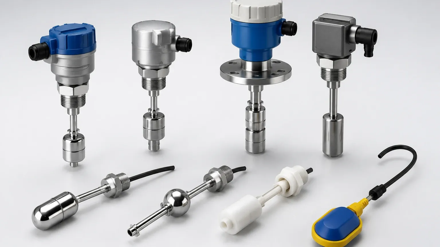
Installation Considerations and Best Practices
Integrating a level sensor into a system requires adhering to strict installation guidelines to ensure accuracy. When reviewing your level sensor 3D model in the context of the tank design, consider the following:
Nozzle Geometry
The height and diameter of the mounting nozzle can significantly impact sensor performance. For radar and ultrasonic sensors, the nozzle should be as short as possible. If the nozzle is too long, the signal may reflect off the internal edges of the pipe before reaching the process media. The 3D model helps verify that the sensor's horn or transducer extends past the nozzle bottom.
Avoiding Obstructions
Internal structures like ladders, pipes, and agitators are common sources of measurement error. When positioning Level Switches or continuous transmitters, the 3D layout must ensure the "signal cone" of the sensor is unobstructed. For a radar sensor with a 10-degree beam angle, the radius of the beam increases as it travels deeper into the tank; this must be modeled to avoid interference.
Environmental Protection
Consider the physical environment. Is the sensor exposed to direct sunlight or heavy rain? The 3D model should help determine if a sunshade or protective housing is required. Furthermore, ensure that cable entries are pointed downwards or looped to prevent moisture from entering the housing via the conduits.
Limitations of 3D Modeling in Level Sensing
While a level sensor 3D model is an invaluable tool, it has limitations that engineers must acknowledge:
* Static Nature: A 3D model represents the sensor in a static state. It does not account for the movement of a flexible cable probe in a turbulent tank or the expansion of components under extreme heat.
* Material Properties: The model shows the shape but not the material's chemical compatibility. An engineer must separately verify that the wetted parts (e.g., SS316L, PTFE, or Hastelloy) are suitable for the process fluid.
* Electronic Configuration: The 3D model does not reflect the software settings, such as damping, false signal suppression, or output scaling (4-20mA/HART), which are critical for functional commissioning.
Frequently Asked Questions (FAQ)
Q: Does the 3D model include the internal electronics?
A: Generally, no. Industrial 3D models focus on the external dimensions, process connections, and electrical interfaces (ports) to facilitate mechanical integration and piping design.
Q: Can I use a generic 3D model for any brand of level switch?
A: It is not recommended. While process connections like a "1-inch NPT" are standardized, the housing size, overall height, and insertion length vary significantly between manufacturers. Using a brand-specific model from a manufacturer like Welk ensures accuracy.
Q: How do I handle 3D models for custom-length probe sensors?
A: For guided wave radar or capacitive probes that are cut-to-length, manufacturers often provide a "configurable" 3D model where the user can input the desired length (L) before downloading the file.
Q: What is the difference between a 'simplified' and a 'detailed' 3D model?
A: Detailed models include every screw and cooling fin, which can slow down large assembly files. Simplified models (often called "envelope models") provide the outer boundaries and connection points, which are usually sufficient for plant layout purposes.
Conclusion
The integration of a level sensor 3d model into the engineering workflow is a critical step in ensuring the reliability and maintainability of industrial level measurement systems. By understanding the measurement principles—whether it be the vibration of Level Switches or the microwave pulses of a radar meter—engineers can use CAD data to prevent costly installation errors.
As industrial processes become more complex, the reliance on accurate digital representations will only grow. Utilizing high-fidelity models from trusted manufacturers ensures that the transition from a digital design to a physical plant is seamless, safe, and efficient. When selecting your next level instrument, always ensure that the corresponding 3D CAD data is available to support your project's design integrity.