Q10 Switch
Q10 Switch
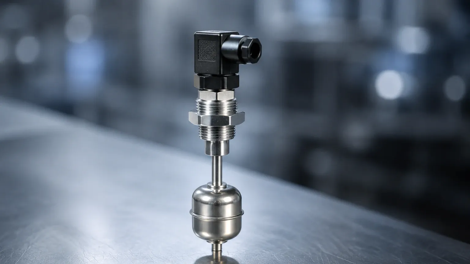
In the landscape of industrial automation and process control, point-level detection serves as a critical safeguard against tank overfills, dry-running pumps, and process inefficiencies. Among the various technologies available, the Q10 switch—a specialized category of compact magnetic float level switches—has emerged as a standard for localized liquid level monitoring. These instruments provide a reliable, low-maintenance solution for detecting specific liquid levels in small to medium-sized vessels, equipment reservoirs, and integrated OEM systems.
As part of the broader family of Level Switches, the Q10 series is characterized by its small footprint, versatility in mounting, and the simplicity of its electromechanical operation. This article provides a technical overview of the Q10 switch, its underlying measurement principles, selection criteria, and the practical considerations necessary for successful deployment in industrial environments.
Understanding the Principles of Magnetic Float Level Switches
The operation of a Q10 switch is based on the fundamental principles of magnetism and the buoyancy of liquids. Unlike complex radar or ultrasonic systems that provide continuous level data, the Q10 switch is a discrete device intended to open or close an electrical circuit at a predetermined height.
The Reed Switch Mechanism
At the core of the Q10 switch is a hermetically sealed reed switch. This component consists of two ferromagnetic blades (reeds) enclosed in a glass envelope filled with an inert gas. The reed switch is positioned within the stationary stem of the device. Because the switch is sealed, it is protected from oxidation, moisture, and the process media, which significantly extends the operational lifespan of the instrument.
The Magnetic Float
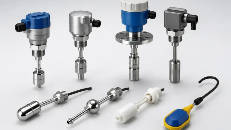
A float containing a permanent magnet is designed to move freely along the stem. As the liquid level in the tank rises or falls, the float moves accordingly. When the float’s internal magnet reaches the exact position of the reed switch, the magnetic field forces the reeds to either touch (closing the circuit) or separate (opening the circuit).
Configuration Options
Q10 switches are typically available in two primary configurations:
1. Normally Open (NO): The circuit is open when the float is at its rest position (usually the bottom of the stem) and closes as the float rises.
2. Normally Closed (NC): The circuit is closed at rest and opens as the float rises.
In many Q10 models, the user can reverse the switch logic by simply removing the retaining clip, flipping the float 180 degrees, and re-installing it. This flexibility is a hallmark of the Q10 switch design, allowing engineers to adapt the device to high-level alarms or low-level cut-offs without changing hardware.
Technical Specifications and Material Compatibility
Selecting the correct Q10 switch requires an understanding of the chemical and physical environment of the application. Because the switch is in direct contact with the liquid, material compatibility is the most critical factor in preventing premature failure.
Common Material Options
* Polypropylene (PP): Best suited for water treatment, general-purpose applications, and diluted acids. It is lightweight and cost-effective but has limited temperature resistance, typically up to 80°C (176°F).
* Stainless Steel (SUS304/316L): Essential for food processing, pharmaceutical applications, and high-pressure environments. Stainless steel models can withstand temperatures exceeding 120°C (248°F) and pressures up to 30 bar (435 psi).
* PVDF (Kynar): Utilized for highly aggressive chemicals, including concentrated acids and halogens. PVDF offers superior chemical resistance and can handle higher temperatures than standard plastics.
Electrical Ratings
Q10 switches are low-power devices. They are generally rated for 10W to 50W of switching capacity. It is vital to note that these switches are intended to trigger control logic (such as a PLC input or a relay coil) rather than directly powering high-draw equipment like pumps or heaters. Attempting to run a motor directly through a Q10 switch will likely weld the reed contacts together due to the inrush current.
Practical Selection Table for Q10 Switches
The following table outlines the key parameters to evaluate when choosing a Q10 switch for industrial use.
| Feature | Specification Range (Typical) | Application Consideration |
| :— | :— | :— |
| Mounting Orientation | Vertical or Horizontal | Depends on tank access and internal space. |
| Switching Voltage | 110V AC / 200V DC (Max) | Ensure compatibility with control system voltage. |
| Switching Current | 0.5A to 1.0A | Use an external relay for higher loads. |
| Temperature Range | -10°C to +120°C (14°F to 248°F) | Material dependent (PP vs. Stainless). |
| Pressure Rating | Atmospheric to 30 bar (435 psi) | Critical for pressurized vessels or boilers. |
| Specific Gravity | Min. 0.65 to 0.85 | The float must be less dense than the liquid. |
| Lead Wire Length | 300mm to 1000mm (Standard) | Custom lengths available for deep sumps. |
Installation Guidelines and Best Practices
Proper installation is paramount to the reliability of a Q10 switch. While the device is mechanically simple, environmental factors can interfere with its operation.
Mounting Position
Q10 switches are available in vertical-mount (top or bottom of the tank) and horizontal-mount (side-wall) versions. For horizontal models, the switch is typically installed through a 1/2" NPT or G1/2 thread. It is essential to ensure the float has sufficient clearance from the tank wall to move through its full arc without obstruction.
Wiring and Circuit Protection
To protect the delicate reed switch from electrical transients, the following measures are recommended:
* Inductive Loads: If the switch is connected to a relay coil or solenoid, a flyback diode (for DC) or an RC snubber (for AC) should be placed across the load to suppress voltage spikes.
* Cable Routing: Avoid routing the switch signal wires in the same conduit as high-voltage power lines to prevent electromagnetic interference (EMI) from causing false triggers.
Turbulence and Sloshing
In tanks with high agitation or inflow, the float may bounce, causing the switch to "chatter." This can lead to rapid cycling of pumps or false alarms. To mitigate this, engineers should:
1. Install the switch in a stilling well (a perforated pipe that dampens surface movement).
2. Program a time-delay into the PLC logic to ensure the level has stabilized before taking action.
Operational Limitations and Environmental Factors
While the Q10 switch is a robust tool, it is not universal. Understanding its limitations prevents misapplication.
1. Viscosity and Coating
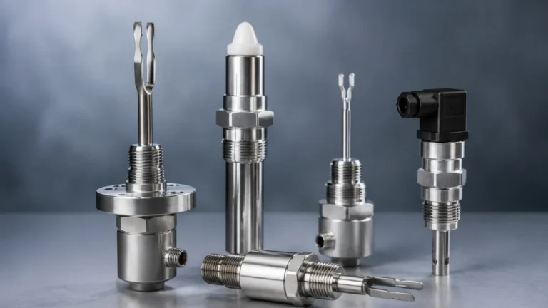
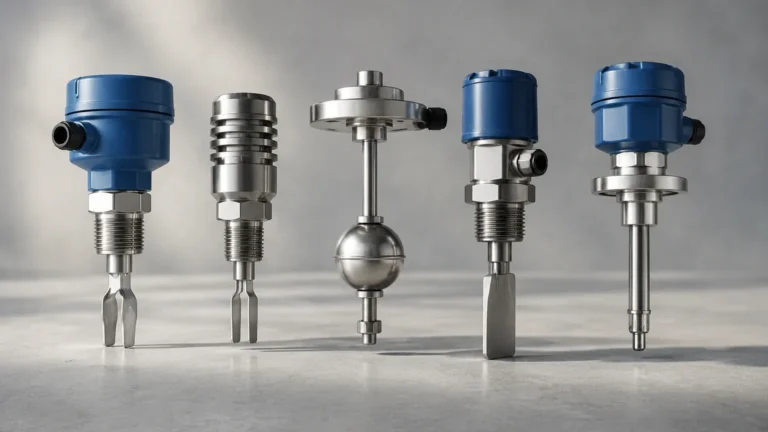
High-viscosity liquids (such as heavy oils or syrups) can create drag on the float, preventing it from moving freely. Similarly, liquids that tend to crystallize or leave heavy deposits can "glue" the float to the stem. For these applications, non-contact methods like ultrasonic sensors or tuning fork switches are often preferred.
2. Ferrous Contamination
Because the Q10 switch relies on a magnet, the presence of iron filings or magnetic particles in the liquid is problematic. These particles will migrate toward the float's magnet, eventually building up enough mass to sink the float or jam the mechanism. Magnetic traps or filters should be installed upstream if ferrous contamination is suspected.
3. Turbulence and Physical Impact
Mechanical floats are susceptible to damage from physical impact. In large tanks where heavy flows are present, the lateral force on the stem can cause it to bend or snap. Proper positioning away from the inlet flow is necessary.
Maintenance and Troubleshooting FAQ
Q: How often should a Q10 switch be inspected?
A: In clean water applications, an annual check is usually sufficient. In chemical or wastewater applications, quarterly inspections are recommended to check for scale build-up or material degradation.
Q: Why is my switch showing continuity even when the float is down?
A: This is often a sign of a "welded" reed switch, caused by an electrical overcurrent. If the contacts have fused together, the unit must be replaced, and a protective relay should be added to the circuit.
Q: Can the Q10 switch be used in hazardous (Ex) areas?
A: Standard Q10 switches are considered "simple apparatus" and can often be used in intrinsically safe circuits when paired with an approved Zener barrier or galvanic isolator. However, always verify the specific ATEX/IECEx certification of the model being used.
Q: Does the orientation of the horizontal switch matter?
A: Yes. Most horizontal Q10 switches have an arrow or a "TOP" marking on the hex head. This ensures the float moves vertically. If installed sideways, the float will not rise with the liquid level.
Conclusion
The Q10 switch remains a staple of industrial level control due to its reliability, ease of integration, and cost-effectiveness. By understanding the interaction between the magnetic float and the reed switch, and by carefully selecting materials that match the process chemistry, engineers can implement effective point-level detection across a wide range of applications. Whether used for high-level overflow protection or low-level pump safety, these Level Switches provide the essential feedback needed to maintain system integrity and operational safety.
For complex installations involving high temperatures, aggressive chemicals, or sanitary requirements, consulting with a manufacturer like Welk ensures that the specific nuances of the Q10 switch design—from thread types to contact ratings—are perfectly aligned with the project's technical demands.