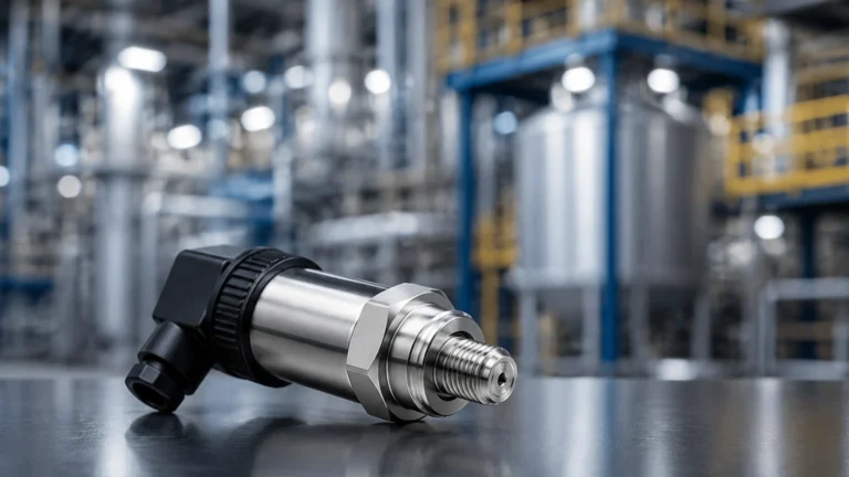
55s
55s
In the landscape of industrial automation, the precision of level measurement directly correlates with operational safety, resource efficiency, and product quality. The 55s series represents a specialized class of high-frequency radar level measurement instruments designed to address the complexities of modern process environments. Whether managing volatile chemicals, wastewater, or high-viscosity oils, understanding the technical nuances of the 55s series is essential for instrumentation engineers and plant managers.
As a professional manufacturer, Welk provides these advanced solutions to meet the rigorous demands of global industries. This guide explores the principles, applications, and selection criteria for 55s technology, serving as a practical engineering reference for those seeking to optimize their level monitoring systems.
Understanding the 55s Measurement Technology
The 55s designation typically refers to a high-frequency (often 80GHz) radar level transmitter. Unlike lower-frequency alternatives, the 55s series utilizes a narrower beam angle and a wider bandwidth, which allows for superior signal separation and accuracy. In industrial B2B applications, this technology is favored for its ability to ignore internal tank obstructions such as agitators, heating coils, and ladders.
The shift toward 80GHz technology in the 55s series has revolutionized how liquid and solid levels are monitored. By operating at a higher frequency, the wavelength is significantly shorter, leading to better reflection off the medium's surface, even when the dielectric constant (εr) is low. This makes the 55s particularly effective for hydrocarbons and other non-conductive fluids.
Core Measurement Principles: Time of Flight and Frequency Modulation
Before selecting a 55s instrument, it is critical to understand the underlying physics that govern its operation. Most 55s radar meters employ Frequency Modulated Continuous Wave (FMCW) technology.
Frequency Modulated Continuous Wave (FMCW)
In FMCW radar, the transmitter emits a continuous signal with a frequency that varies over time (a linear frequency ramp). The signal travels to the surface of the medium, reflects, and returns to the receiver. Because the emitted frequency is constantly changing, there is a frequency difference between the transmitted signal and the received signal. This difference is directly proportional to the time of flight, which allows the internal processor to calculate the distance with millimeter precision.
Beam Angle and Focusing
A defining characteristic of the 55s series is its small beam angle. At 80GHz, a standard 55s unit might have a beam angle as narrow as 3 degrees. This tight focus ensures that the radar energy is concentrated on the product surface rather than the vessel walls. This is a significant advantage over 26GHz or 6GHz radars, which have wider beams that often trigger false echoes from tank internals.
Technical Specifications and Performance Parameters
When evaluating a 55s level meter, engineers must look beyond the basic range and accuracy. The performance of these units is defined by several key parameters that dictate their suitability for specific process conditions.
| Parameter | Typical 55s Specification | Imperial Equivalent |
| :— | :— | :— |
| Frequency | 76 GHz – 81 GHz | N/A |
| Measurement Range | Up to 120 meters | 393.7 feet |
| Measurement Accuracy | ±1 mm to ±2 mm | ±0.039 to ±0.078 inches |
| Process Temperature | -40°C to +200°C | -40°F to +392°F |
| Process Pressure | -0.1 to 4.0 MPa | -14.5 to 580 PSI |
| Beam Angle | 3° to 8° (depending on antenna) | N/A |
| Signal Output | 4-20mA / HART, RS485/Modbus | N/A |
Dielectric Constant Sensitivity
The 55s series is highly sensitive to the dielectric constant of the material being measured. Materials with a high dielectric constant, such as water (εr ≈ 80), reflect radar waves strongly. Materials with a low dielectric constant, such as plastic pellets or certain oils (εr < 2), are more challenging. The high-frequency nature of the 55s allows it to detect these weak reflections more reliably than lower-frequency models.
Application-Specific Selection for 55s Instruments
The versatility of the 55s series makes it applicable across various sectors. However, the specific configuration must match the application's physical and chemical requirements.
Chemical and Petrochemical Processing
In chemical storage, the 55s is often used for corrosive liquids. Because the radar is non-contact, the sensor remains isolated from the medium. Welk offers 55s units with PTFE-enclosed antennas, providing maximum chemical resistance. For pressurized tanks, the ability of the 55s to measure through sight glasses or specialized nozzles is a distinct advantage.
Water and Wastewater Management
For large-scale reservoirs and open-channel flow measurement, the 55s provides a maintenance-free alternative to ultrasonic sensors. Unlike ultrasonic waves, radar signals are not affected by air temperature fluctuations, wind, or steam. This ensures consistent readings in wastewater sumps where condensation and vapor are common.
Food and Beverage Industry
Hygiene is paramount in food processing. The 55s series can be equipped with hygienic flange connections and polished surfaces to prevent bacterial growth. Its ability to measure accurately despite the presence of foam (to a certain extent) or heavy agitation makes it ideal for fermentation tanks and mixing vessels.
For a comprehensive overview of available technologies and specific model variations, professionals should consult the Main Page for detailed product specifications and application support.
Installation Guidelines and Environmental Considerations
Correct installation is the most influential factor in the longevity and accuracy of a 55s level meter. Even the most advanced 80GHz radar will fail if poorly positioned.
Nozzle Design and Placement
The 55s should be installed in a location where the radar beam has an unobstructed path to the liquid surface. While the narrow beam of the 55s is forgiving, it should not be placed too close to the tank wall. A general rule is to maintain a distance of at least 200mm (approx. 8 inches) from the wall to prevent interference from weld seams or wall buildup.
Avoiding Obstructions
Avoid installing the sensor directly above the filling inlet. The turbulence and splashing caused by incoming material will create "noise" in the radar signal, leading to erratic readings. If an agitator is present, the 55s should be positioned such that the beam hits the surface in a relatively calm area, ideally halfway between the shaft and the tank wall.
Blocking Distance (Dead Zone)
Every radar sensor has a minimum distance it can measure, known as the blocking distance or dead zone. For many 55s models, this is typically around 0.1m to 0.3m (4 to 12 inches). Ensure that the maximum expected level of the tank does not enter this zone, as the sensor will lose track of the level.

Maintenance and Operational Reliability
One of the primary B2B selling points of the 55s series is its low maintenance requirement. Since there are no moving parts and no contact with the medium, mechanical wear is non-existent. However, periodic checks are recommended to ensure optimal performance.
1. Antenna Cleaning: In applications with heavy vapor or dust, the antenna face may accumulate buildup. While the 55s is designed to penetrate some buildup, excessive coating can attenuate the signal. A simple wipe-down with a compatible solvent is usually sufficient.
2. Signal Diagnostics: Modern 55s units provide diagnostic data via HART or Modbus. Monitoring the "Echo Curve" or signal-to-noise ratio can help predict when maintenance is needed before a failure occurs.
3. Calibration Verification: While the factory calibration of a 55s is highly stable, annual verification against a manual dip tape or a secondary reference is standard practice in regulated industries.
Limitations and Challenges
Despite its advanced capabilities, the 55s is not a universal solution for every scenario. Engineers must be aware of its limitations:
* Heavy Foam: While 80GHz radar is better than ultrasonic in many foamy applications, extremely thick, dense foam (like shaving cream) can absorb the radar signal entirely. In such cases, a guided wave radar or a hydrostatic transmitter might be more appropriate.
* Extreme Dust: In solid level measurement (e.g., cement silos), extreme dust during filling can attenuate the high-frequency signal. While the 55s is generally robust, specific antenna designs with air-purge systems are often required for these environments.
* Vacuum Conditions: While radar works in a vacuum, the mechanical seals of the 55s unit must be rated for vacuum service to prevent damage to the internal electronics.
Frequently Asked Questions (FAQ)
Q: Can the 55s measure through a plastic tank wall?
A: Yes, because radar waves can penetrate non-conductive materials like plastic or fiberglass, a 55s can often measure the level from outside the tank, provided the wall thickness is not excessive and the material has a low dielectric constant.
Q: How does the 55s compare to ultrasonic sensors?
A: The 55s (radar) is generally superior in accuracy and reliability. It is unaffected by vacuum, pressure, or air temperature changes, whereas ultrasonic sensors rely on the speed of sound, which varies with air density and temperature.
Q: What is the lifespan of a Welk 55s level meter?
A: With proper installation and minimal environmental interference, these units typically have an operational lifespan exceeding 10 years due to their solid-state electronics and non-contact nature.
Conclusion
The 55s series of level measurement instruments represents the pinnacle of high-frequency radar technology. By offering millimeter precision, narrow beam angles, and robust performance in challenging industrial environments, it has become a standard for B2B operations in water treatment, chemical processing, and oil and gas. When selecting a 55s unit, careful consideration of the dielectric constant, tank geometry, and process conditions will ensure a reliable, cost-effective solution for years to come. For further technical guidance and to explore the full range of industrial level sensors, visit the Main Page to connect with application specialists.