API 2350 5th Edition Category 3 Tanks Requirements
API 2350 5th Edition Category 3 Tanks Requirements
The American Petroleum Institute (API) Standard 2350, specifically the 5th Edition, serves as the definitive guideline for overfill protection for storage tanks in petroleum facilities. As industrial operations move toward higher levels of automation and stricter safety protocols, understanding the nuances of "Category 3" tank requirements becomes essential for plant engineers and safety officers. Category 3 represents the highest tier of automation within the standard, necessitating integrated systems that function independently of manual intervention to prevent catastrophic overfill events.
For facilities transitioning to or maintaining Category 3 compliance, the selection of level measurement technology is not merely a matter of operational efficiency but a critical component of a Safety Instrumented System (SIS). This guide details the technical requirements, measurement principles, and selection criteria necessary to meet API 2350 5th Edition standards for Category 3 tanks.
Understanding the API 2350 Categorization
API 2350 classifies tanks based on the level of instrumentation and the type of personnel involvement required to prevent an overfill. To understand Category 3, it is helpful to contrast it with the lower categories:
1. Category 1: Relies on manual procedures and local level indicators. There is no remote monitoring or automatic signaling.
2. Category 2: Includes an Automatic Tank Gauging (ATG) system and a high-level alarm (HLA) that alerts an operator. The operator must then take manual action to stop the flow.
3. Category 3: Requires both an ATG and an independent Automatic Overfill Prevention System (AOPS). In this category, the system must be capable of terminating the receipt of liquid without any human intervention.
The 5th Edition emphasizes a risk-based approach, requiring operators to perform a formal risk assessment to determine if a tank should be classified as Category 3. Generally, tanks with high flow rates, those located in environmentally sensitive areas, or those where the "Time to Overfill" is too short for human response are candidates for Category 3.
Measurement Principles for Overfill Protection
Before selecting hardware for a Category 3 system, engineers must understand the physical principles governing level detection. In Category 3 applications, two distinct types of measurement are typically required: continuous level measurement (for the ATG) and point level or continuous measurement (for the AOPS).
Radar Level Measurement (FMCW and Pulsed)
Radar technology is the industry standard for petroleum storage due to its non-contact nature and high accuracy. It operates on the Time of Flight (ToF) principle. A sensor emits electromagnetic pulses (or a continuous frequency-modulated wave) that reflect off the liquid surface and return to the receiver. The distance is calculated based on the time taken for the signal to travel.
* 80 GHz Radar: High-frequency radar offers a narrow beam angle, which is ideal for avoiding internal tank obstructions like heating coils or agitators. It provides accuracy within ±1 mm, making it suitable for both ATG and safety functions.
* Guided Wave Radar (GWR): Uses a probe to guide the signal. It is highly effective for liquids with low dielectric constants or in tanks with heavy foam, though it is a contact-based technology.
Ultrasonic Level Measurement
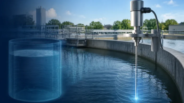
Ultrasonic sensors emit sound waves that reflect off the surface of the liquid. While cost-effective, their use in petroleum tanks is often limited by the presence of vapors, pressure changes, and temperature fluctuations that affect the speed of sound. In Category 3 environments, ultrasonic is more common in water treatment or chemical storage rather than high-volatility hydrocarbon tanks.
Hydrostatic Pressure
This principle measures the pressure exerted by the liquid column. While reliable for many industrial applications, it requires constant liquid density to remain accurate. Since petroleum products can vary in density with temperature, hydrostatic transmitters are often used as secondary verification rather than the primary AOPS sensor in Category 3 setups.
Technical Requirements for Category 3 Tanks
The 5th Edition of API 2350 mandates several specific technical layers for Category 3 compliance. The goal is to ensure that even if the primary gauging system fails, a secondary, independent system will prevent the overfill.
1. Independence and Redundancy
A fundamental requirement for Category 3 is the independence of the AOPS from the ATG. This means:
* Separate Sensors: The sensor used for the high-high (HH) alarm and automatic shutdown must be physically different from the sensor used for inventory management.
* Separate Logic Solvers: The signal from the safety sensor should ideally go to a dedicated logic solver (such as a Safety PLC) rather than the standard process control system.
* Separate Final Control Elements: The AOPS must be able to trigger a dedicated emergency shutdown valve (ESV) or stop a pump independently of the process control valves.
2. Level Definitions and Alarm Setpoints
API 2350 defines specific levels that must be calculated and programmed into the system:
* Critical High Level (CHL): The highest level the liquid can reach before an overfill occurs (e.g., the top of the tank or the rim of a floating roof).
* High-High (HH) Level: The level at which the AOPS is triggered. This must be set low enough to allow the final control element (valve or pump) to fully stop the flow before the liquid reaches the CHL.
* Maximum Working Level (MWL): The highest level allowed during normal operations.
3. Response Time Calculation
For Category 3 tanks, the "Response Time" is critical. It includes the time for the sensor to detect the HH level, the logic solver to process the signal, and the valve to close completely. Engineers must ensure that the volume between the HH level and the CHL is greater than the volume delivered during the total response time at the maximum possible flow rate.
Instrumentation Selection Table
When designing a system to meet API 2350 Category 3, the following table provides a comparison of common technologies used for the AOPS and ATG components.
| Technology | Suitability for ATG | Suitability for AOPS | Pros | Cons |
| :— | :— | :— | :— | :— |
| 80 GHz Free-Space Radar | Excellent | Excellent | High accuracy, non-contact, ignores vapors. | Higher initial cost. |
| Guided Wave Radar (GWR) | Good | Excellent | Unaffected by turbulence or foam. | Probe can be damaged by heavy debris. |
| Vibrating Fork (Switch) | N/A | Good | Highly reliable point level detection. | No continuous data; contact-based. |
| Hydrostatic Transmitter | Fair | Fair | Robust and simple. | Dependent on density accuracy. |
| Servo Gauges | Excellent | Poor | Extremely accurate for custody transfer. | Mechanical parts require high maintenance. |
For a comprehensive range of instruments that meet these industrial standards, engineers can Review product options and application support to find solutions tailored to specific tank geometries and media types.
Installation and Engineering Considerations
Correct installation is as vital as the technology itself. Even the most advanced radar meter will fail to meet API 2350 requirements if installed improperly.
* Nozzle Positioning: Sensors should be located away from the inlet flow to prevent turbulence or false readings caused by the incoming stream. For Category 3, ensuring the AOPS sensor has a clear "view" of the liquid surface is paramount.
* Stilling Wells: In tanks with internal structures or significant surface agitation, installing the level sensor inside a stilling well (a vertical pipe) can provide a stable surface for measurement. However, the well must be properly vented and free of scale buildup.
* Environmental Protection: In petroleum environments, instruments must be explosion-proof (Ex d) or intrinsically safe (Ex i) and have appropriate Ingress Protection (IP) ratings to withstand outdoor exposure.
* Bypass Chambers: For tanks where internal access is restricted, external bypass chambers can house the AOPS sensors. This allows for maintenance and proof testing without taking the tank out of service.
Proof Testing and Maintenance
API 2350 5th Edition places heavy emphasis on the lifecycle management of overfill protection systems. For Category 3 tanks, regular proof testing is mandatory to ensure the safety loop is functional.
1. Visual Inspection: Checking for corrosion, loose wiring, or damage to the sensor housing.
2. Functional Testing: Simulating a high-level condition to verify that the AOPS sensor sends the correct signal to the logic solver and that the valve actually closes.
3. Calibration Verification: Comparing the ATG reading against a manual dip or a secondary reference to ensure accuracy within the required tolerances (typically ±3 mm to ±25 mm depending on the tank size and risk profile).
Common Risks and Limitations
Despite the advanced nature of Category 3 systems, certain risks remain:
* Common Mode Failure: If the ATG and AOPS use the same power supply or the same cable conduit, a single incident (like a fire or electrical surge) could disable both systems. True Category 3 compliance requires physical and electrical separation.
* Paraffin or Scale Buildup: In crude oil tanks, buildup on sensors or inside stilling wells can cause "frozen" readings, where the sensor reports a safe level while the tank is actually overfilling.
* Communication Latency: In large facilities, the delay in transmitting a signal from a remote tank farm to a central control room must be accounted for in the response time calculation.
FAQ: API 2350 Category 3 Requirements
Q: Can I use the same radar sensor for both ATG and AOPS?
A: No. API 2350 Category 3 requires independence. While you can use two radar sensors, they must be separate units to ensure that a failure in one does not affect the other.
Q: Is a manual high-level alarm enough for Category 3?
A: No. A manual alarm (Category 2) requires an operator to respond. Category 3 requires an automatic shutdown (AOPS) that works without human intervention.
Q: How often must Category 3 systems be tested?
A: The frequency is determined by the risk assessment and the Safety Integrity Level (SIL) of the components, but it is typically performed annually or semi-annually.
Q: Does API 2350 apply to pressurized tanks (LPG/LNG)?
A: API 2350 primarily covers atmospheric storage tanks. Pressurized vessels are generally covered by other standards like API 2510, though the principles of automated overfill protection are similar.
Conclusion
Compliance with API 2350 5th Edition Category 3 requirements is a significant undertaking that requires a blend of rigorous risk assessment, precise engineering, and high-quality instrumentation. By implementing independent, automated systems—preferably utilizing non-contact radar technology—facilities can drastically reduce the risk of overfill incidents, protecting both the environment and the bottom line. When selecting equipment, always prioritize sensors that offer self-diagnostics and high reliability to ensure the safety loop remains integrity-ready at all times. For those seeking specialized hardware for these applications, Welk provides a variety of industrial-grade solutions through their Main Page.
Download API 2350 5th Edition Category 3 Tanks Requirements as a PDF