API 2350 5th Edition Key Changes Summary
API 2350 5th Edition Key Changes Summary
In the petroleum and chemical industries, overfill prevention is a critical safety requirement. The American Petroleum Institute (API) Standard 2350, "Overfill Protection for Storage Tanks in Petroleum Facilities," serves as the primary guideline for preventing tank overfills in atmospheric storage tanks. With the release of the 5th edition, the standard underwent a significant evolution, shifting from a purely prescriptive set of rules to a more comprehensive, risk-based management system. This API 2350 5th edition key changes summary explores the technical updates, the introduction of the Overfill Management System (OMS), and the implications for selecting level measurement instrumentation.
The Shift to an Overfill Management System (OMS)
One of the most fundamental changes in the 5th edition is the formalization of the Overfill Management System (OMS). Unlike previous versions that focused heavily on the hardware—the level switches and transmitters—the 5th edition recognizes that equipment is only one part of a safe operation.
The OMS is a systematic approach that integrates personnel, procedures, and equipment. It requires facilities to document how they manage the entire lifecycle of overfill prevention, including risk assessment, system design, operational procedures, and maintenance schedules. For engineers and facility managers, this means that installing a high-quality radar level meter is no longer sufficient for compliance; there must also be a documented process for how that meter is tested, how alarms are handled by operators, and how the system is audited.
Expanded Scope and Tank Classification
Historically, API 2350 focused on large-scale storage tanks. The 5th edition expanded the scope to include a broader range of facilities.
Inclusion of Smaller Tanks
While the 4th edition primarily targeted tanks over 1,320 gallons (approximately 5,000 liters), the 5th edition clarifies that the principles of overfill protection should be applied to any tank where an overfill could result in a significant safety or environmental hazard. This expansion ensures that smaller chemical storage or additive tanks, which may still pose significant risks, are brought under the umbrella of formal overfill management.
Categorization of Tanks
The standard continues to categorize tanks based on the level of automation and the presence of personnel during receiving operations. This categorization is vital for determining the required instrumentation:
1. Category 1 (Manual): These are tanks where the operator is physically present at the tank or at a local control station during the entire receipt. Overfill prevention relies on manual level gauging and manual valve closure.
2. Category 2 (Automated with Manual Intervention): These systems use level sensors to transmit data to a remote location (like a control room). If an alarm is triggered, an operator must take manual action to stop the flow.
3. Category 3 (Fully Automated): These systems include an independent Overfill Prevention System (OPS) that automatically terminates the flow of liquid without operator intervention. These are often designed as Safety Instrumented Systems (SIS) following the IEC 61511 standard.
Risk-Based Methodology and SIL Alignment
A pivotal change in the API 2350 5th edition key changes summary is the mandate for a formal risk assessment. The standard now requires facility owners to conduct a risk assessment for every tank to determine the appropriate category and the necessary level of redundancy.
This risk-based approach aligns API 2350 more closely with international safety standards like IEC 61511. If a risk assessment determines that a tank requires a Category 3 system, the instrumentation must often meet specific Safety Integrity Level (SIL) ratings. For example, a high-risk flammable liquid storage tank might require a SIL 2 or SIL 3 rated level transmitter to ensure the probability of failure on demand is sufficiently low.
Redefining Levels and Response Times
The 5th edition provides clearer definitions for the various levels within a tank, which is essential for calibrating industrial level measurement instruments.
* Critical High Level (CHL): The highest point in the tank that, if exceeded, results in an overfill (e.g., liquid entering the vent or damaging the roof).
* High-High (HH) Level: The level at which an emergency alarm is triggered or an automated shutdown is initiated.
* High (H) Level: A level used for operational control, providing an early warning to the operator.
* Maximum Working Level (MWL): The highest level used during normal operations.
Calculation of Response Time
The 5th edition places a heavy emphasis on "Response Time." This is the duration required to safely terminate a receipt once an alarm is triggered. It includes the time for the sensor to detect the level, the time for the signal to reach the operator (or controller), and the time required for valves to close and pumps to stop. For Category 2 systems, the standard typically suggests a minimum operator response time of 30 to 60 minutes, depending on the facility's complexity. If the physical space between the HH alarm and the CHL is insufficient to accommodate this response time at the maximum flow rate, the flow rate must be reduced, or the HH level must be lowered.
Measurement Principles for API 2350 Compliance
To meet the requirements of the 5th edition, measurement technologies must be reliable, accurate, and capable of providing the necessary diagnostics. Before selecting a device, it is important to understand how different principles interact with the standard’s requirements.
Radar Level Measurement
Radar level meters, including both non-contact and guided wave (GWR) varieties, are the preferred choice for Category 2 and 3 tanks. They offer high accuracy (often within ±2 mm) and have no moving parts, which reduces the risk of mechanical failure.
* Non-contact Radar: Ideal for corrosive or viscous liquids as the sensor does not touch the media. It provides continuous level monitoring, which is essential for calculating the rate of fill.
* Guided Wave Radar: Excellent for liquids with low dielectric constants or in tanks with internal turbulence. The probe ensures the signal remains focused.
Ultrasonic Level Sensors
Ultrasonic sensors are cost-effective for smaller, non-pressurized tanks. However, they can be affected by vapor layers, foam, or temperature fluctuations. In the context of API 2350, they are generally used for non-hydrocarbon applications or in Category 1 and 2 environments where the risks are lower.
Point Level Switches
While continuous level measurement is preferred for monitoring, independent point level switches (such as tuning fork or magnetic float switches) are frequently used as the "High-High" alarm sensor. API 2350 emphasizes independence; therefore, the HH sensor should ideally be a different technology or at least a separate device from the primary level transmitter to avoid common-cause failures.

Selection Table: Level Instrumentation for API 2350
| Technology | API 2350 Category | Pros | Cons | Best Use Case |
| :— | :— | :— | :— | :— |
| Non-Contact Radar | 2 & 3 | Highly accurate, no moving parts, SIL rated options. | Higher initial cost. | Large hydrocarbon tanks, high-risk chemicals. |
| Guided Wave Radar | 2 & 3 | Unaffected by vapors or turbulence, precise. | Probe can be fouled by sticky media. | Tanks with internal obstructions or low dielectrics. |
| Tuning Fork Switch | 2 & 3 (as HH) | Very reliable, self-monitoring, compact. | Point measurement only. | Independent High-High alarm/shutdown. |
| Ultrasonic Sensor | 1 & 2 | Low cost, easy installation. | Sensitive to foam, vapor, and vacuum. | Water treatment, non-volatile chemical storage. |
| Magnetic Level Gauge | 1 & 2 | Local visual indication plus transmitter. | Mechanical parts can stick. | Process tanks requiring local and remote monitoring. |
Installation and Maintenance Considerations
Compliance with API 2350 5th edition goes beyond choosing the right meter; the installation must support the system's integrity.
1. Independence: For Category 3 systems, the Overfill Prevention System (OPS) must be physically and electrically independent from the Tank Gauging System (TGS). This means separate tank nozzles, separate power supplies, and separate cabling.
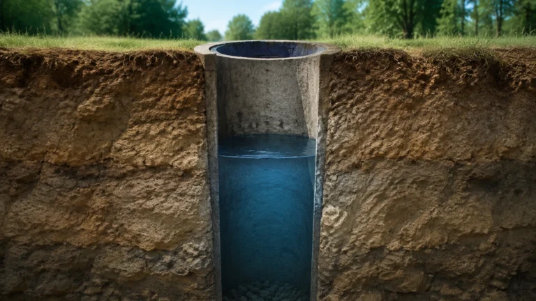
2. Stilling Wells: For radar installations in tanks with internal structures or heavy turbulence, stilling wells (pipes) are recommended to ensure a clean signal and accurate measurement.
3. Proof Testing: The 5th edition mandates regular proof testing of the overfill protection system. The frequency of these tests is determined by the risk assessment and the equipment's failure rate. Modern level meters with "remote proof test" capabilities allow operators to verify the sensor's functionality without climbing the tank or manually raising the liquid level, significantly improving safety and reducing downtime.
4. Environmental Factors: Consider the influence of ambient temperature and solar heating. In extreme climates, sunshades or heated enclosures may be necessary to maintain instrument electronics within their specified operating range.
Common Risks in Implementation
Even with the best equipment, certain risks can jeopardize API 2350 compliance:
* Common-Cause Failure: Using the same technology and the same manufacturer for both the primary level gauge and the high-level alarm can lead to both failing under the same conditions (e.g., heavy foam or steam).
* Inadequate Response Time: Failing to account for the closing time of motor-operated valves (MOVs) can result in an overfill even if the alarm triggers correctly.
* Bypassing Alarms: Without a strong OMS culture, operators may bypass alarms to speed up transfers, negating the safety benefits of the instrumentation.
Frequently Asked Questions
Q: Does API 2350 5th edition require me to replace my old mechanical float switches?
A: Not necessarily. If your risk assessment shows that the existing system meets the required safety integrity and the response times are adequate, they can remain. However, many facilities are upgrading to electronic switches or radar because they offer better reliability and self-diagnostics.
Q: How often must I perform a proof test?
A: The standard does not set a universal interval. It must be determined by the facility based on the risk assessment, the manufacturer’s recommendations, and the historical performance of the equipment. Annual testing is a common industry starting point.
Q: Can one radar gauge provide both the operational level and the high-high alarm?
A: For Category 1 and 2, it is possible, but for Category 3 (SIS), API 2350 and IEC 61511 generally require an independent sensor for the overfill protection function to ensure redundancy.
Conclusion
The API 2350 5th edition key changes summary highlights a move toward a more sophisticated and holistic approach to tank safety. By integrating hardware, software, and human procedures into an Overfill Management System, petroleum facilities can significantly reduce the risk of catastrophic spills. For engineers, this requires a careful selection of robust level measurement technologies that not only provide accurate data but also support the diagnostic and independence requirements of modern safety standards. For more information on selecting the right hardware for your specific application, you can Review product options and application support on our Main Page.
When implementing these changes, always prioritize the risk assessment results and ensure that every component of the overfill prevention chain—from the sensor in the tank to the valve on the inlet line—is designed to work in harmony under emergency conditions.