Gas and Oil Separation Plant
Gas and Oil Separation Plant
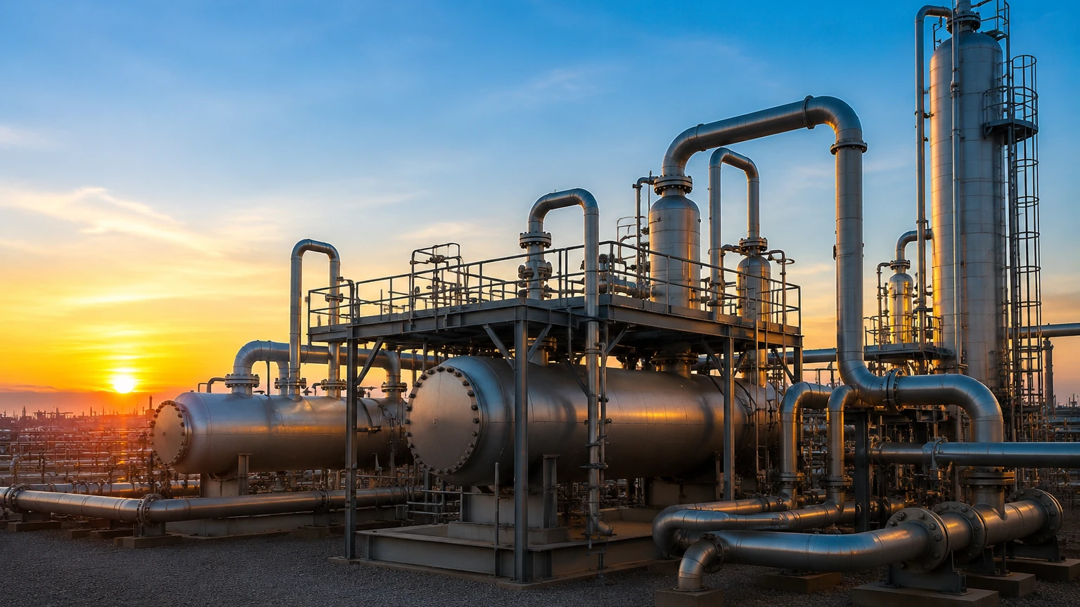
In the upstream oil and gas industry, the gas and oil separation plant (GOSP) serves as the primary processing hub where raw wellhead fluids are transformed into transportable products. The fluids emerging from a well are rarely pure; they typically consist of a complex mixture of crude oil, natural gas, produced water, and various solids like sand or silt. To meet pipeline specifications and refinery requirements, these components must be separated efficiently and safely.
At the heart of every gas and oil separation plant is the requirement for precise process control. Level measurement is perhaps the most critical parameter within this environment. Accurate level data ensures that separators operate within their design limits, preventing equipment damage and environmental hazards while maximizing the recovery of hydrocarbons. This article explores the engineering principles of level measurement within a GOSP and provides a guide for selecting the right instrumentation for these demanding applications.
The Role of Level Measurement in GOSP Operations
A gas and oil separation plant functions through a series of stages, primarily using gravity and pressure differentials to separate phases. The process usually begins with a slug catcher or a high-pressure separator, followed by intermediate and low-pressure stages.
In a typical three-phase separator, the vessel must maintain three distinct zones: a gas zone at the top, an oil zone in the middle, and a water zone at the bottom. Level instruments are tasked with two primary roles:
1. Total Level Control: Monitoring the overall liquid level to prevent "carry-over" (liquid entering the gas outlet) or "carry-under" (gas entering the liquid outlet).
2. Interface Level Control: Monitoring the boundary between oil and water. This is essential for ensuring that the oil sent to the stabilizers is dry and that the produced water sent for treatment contains minimal oil.
Failure to maintain these levels can lead to "tripping" the plant, resulting in costly downtime, or worse, sending water-contaminated oil into export pipelines which can cause severe corrosion.
Measurement Principles for GOSP Applications
Before selecting an instrument for a gas and oil separation plant, it is vital to understand the physical principles governing different measurement technologies. Each has strengths and limitations based on the fluid properties and vessel conditions.
1. Radar Level Measurement
Radar technology is the industry standard for GOSP applications due to its reliability in high-pressure and high-temperature environments. It is divided into two main types:
* Guided Wave Radar (GWR): This technology utilizes Time Domain Reflectometry (TDR). A low-energy electromagnetic pulse is sent down a probe (waveguide). When the pulse hits a medium with a different dielectric constant (such as the oil surface or the oil-water interface), a portion of the energy is reflected back. Because the speed of light is constant, the time it takes for the pulse to return is used to calculate the distance. GWR is particularly effective for interface measurement because the pulse can pass through the upper low-dielectric layer (oil) and reflect off the high-dielectric layer (water).
* Non-Contact Radar: This uses Frequency Modulated Continuous Wave (FMCW) or pulse technology to transmit signals through the vapor space. It is ideal for total level measurement where the probe should not touch the medium, such as in highly corrosive or viscous fluids.
2. Ultrasonic Level Measurement
Ultrasonic sensors emit high-frequency sound waves that reflect off the liquid surface. The time-of-flight determines the distance. While cost-effective, ultrasonic technology is often limited in a gas and oil separation plant. High pressure significantly alters the speed of sound, and the presence of heavy vapors or foam can absorb the acoustic signal, leading to inaccuracies. It is generally reserved for atmospheric produced-water tanks or chemical storage.
3. Hydrostatic Level Measurement
This principle relies on the relationship between liquid height and pressure ($P = \rho \cdot g \cdot h$). By measuring the pressure at the bottom of a vessel and compensating for the top-side vapor pressure (using a differential pressure transmitter), the liquid level can be calculated. While robust, its accuracy depends entirely on a constant fluid density. In a GOSP, where oil density can change with temperature and gas content, hydrostatic sensors require frequent recalibration.
4. Magnetic Level Gauges (MLG)
MLGs consist of a bypass chamber attached to the side of the vessel. A float containing a magnet moves with the liquid level, flipping external magnetic flags to provide a visual indication. They are often paired with reed-chain transmitters or magnetostrictive sensors for remote electronic signaling. These are highly valued in GOSP environments for their mechanical simplicity and the fact that they provide a local visual backup that does not require power.
Key Evaluation Criteria for GOSP Instrumentation
When designing or upgrading a gas and oil separation plant, engineers must evaluate several factors to ensure the longevity and accuracy of level instruments.
| Feature | Guided Wave Radar | Non-Contact Radar | Hydrostatic (DP) | Magnetic Level Gauge |
| :— | :— | :— | :— | :— |
| Interface Measurement | Excellent | Limited | Possible (if $\Delta\rho$ is stable) | Excellent (with specific float) |
| Pressure Resistance | Up to 400 bar | Up to 160 bar | High | Up to 250+ bar |
| Foam Sensitivity | Low | Moderate | None | None |
| Vapor Sensitivity | Low | Moderate | High (requires compensation) | None |
| Maintenance | Low | Very Low | Moderate | Moderate (cleaning of chamber) |
| Installation | Top-mounted probe | Top-mounted | Side/Bottom nozzles | Side-mounted (Bypass) |
Process Conditions and Material Selection
Fluid in a gas and oil separation plant is often "sour," meaning it contains Hydrogen Sulfide ($H_2S$). This requires all wetted parts to comply with NACE MR0175/ISO 15156 standards to prevent sulfide stress cracking. Common materials include 316L Stainless Steel, Hastelloy C-276, or Monel.
Furthermore, the presence of paraffin or wax in many crude oils can lead to buildup on probes and floats. In these cases, non-contact radar or heated bypass chambers for magnetic gauges are preferred to prevent mechanical sticking or signal attenuation.
Installation Considerations in a GOSP Environment
Proper installation is as critical as the choice of technology. In a gas and oil separation plant, vessels are often subject to high turbulence near the inlets.
1. Stilling Wells and Bypass Chambers: To protect the measurement from turbulence and foam, sensors are often installed in stilling wells (internal pipes) or bypass chambers (external pipes). This provides a calm surface for the radar or float to operate.
2. Nozzle Positioning: Nozzles should be located away from the fluid inlet to avoid the direct impact of the incoming stream. For interface measurement, the instrument must be positioned where the oil and water have had sufficient residence time to separate.
3. Vapor Space Management: In high-pressure separators, the gas phase can become very dense, affecting the propagation speed of radar waves. Advanced radar transmitters include gas phase compensation features, using a reference reflection to adjust the calculation in real-time.
For a comprehensive look at available hardware and technical specifications, engineers can Review product options and application support on the Welk Main Page.
Common Risks and Limitations
Operating a gas and oil separation plant involves managing several physical phenomena that can interfere with level measurement:
* Emulsion Layers (Rag Layers): In many GOSPs, a thick layer of emulsion (a mixture of oil and water) forms between the two phases. This "rag layer" can be several centimeters thick. GWR is usually the best choice here, as it can be configured to detect the top of the emulsion or the "clean" water level, but it requires careful commissioning.
* Foaming: High-pressure gas breaking out of the oil can create foam. Foam can scatter non-contact radar signals or cause "false high" readings in displacement-based sensors. Radar units with high sensitivity and signal processing algorithms are required to "see through" the foam to the true liquid surface.
* Sand Accumulation: Solids settling at the bottom of a separator can bury hydrostatic sensors or jam the bottom of a magnetic gauge chamber. Regular flushing ports should be included in the design of bypass chambers.
Frequently Asked Questions (FAQs)
Q: Why is GWR preferred over traditional displacers in modern GOSPs?
A: Traditional displacer transmitters rely on buoyancy and torque tubes. They have moving parts that are prone to wear, sticking due to wax, and inaccuracies if the fluid density changes. GWR has no moving parts and is largely unaffected by density fluctuations, making it much lower maintenance.
Q: How do you handle level measurement in a slug catcher?
A: Slug catchers experience sudden, massive inflows of liquid. This requires instruments with very fast response times and high mechanical integrity. Non-contact radar is often used here because there is no probe to be bent or damaged by the force of the incoming "slug."
Q: Can one instrument measure both total level and interface?
A: Yes, modern Guided Wave Radar transmitters are capable of providing dual outputs—one for the upper liquid level (oil) and one for the interface level (water)—provided there is a sufficient difference in the dielectric constants of the two fluids (typically a difference of at least 10).
Conclusion
The efficiency of a gas and oil separation plant is intrinsically linked to the accuracy of its level measurement systems. By understanding the underlying principles of radar, hydrostatic, and magnetic technologies, and by accounting for the specific challenges of the GOSP environment—such as H2S content, foam, and emulsion layers—operators can ensure stable production and high-quality product export.
When selecting instrumentation, always prioritize materials that meet NACE standards and technologies that offer diagnostics capable of identifying buildup or signal loss before they lead to process failure. For detailed technical data and selection guides for industrial level measurement, visit the Main Page of the Welk website.