Cooling Tower Vibration Sensor
Cooling Tower Vibration Sensor
In the landscape of industrial cooling and HVAC systems, the cooling tower serves as a critical heat rejection component. However, the mechanical assembly within these towers—comprising large-diameter fans, gearboxes, drive shafts, and motors—is subject to significant mechanical stress. A cooling tower vibration sensor is an essential diagnostic tool designed to monitor the structural integrity and mechanical health of these components in real-time. By detecting early signs of imbalance, misalignment, or bearing wear, these sensors prevent catastrophic failures, ensure personnel safety, and optimize maintenance schedules.
Understanding Vibration Monitoring in Cooling Towers
Cooling towers operate in demanding environments characterized by high humidity, varying temperatures, and constant exposure to water treatment chemicals. The mechanical equipment is often mounted at the top of the tower, making manual inspection difficult and infrequent.
Mechanical vibration in a cooling tower is typically the result of centrifugal forces acting on rotating parts. While some level of vibration is inherent in any operating machinery, an increase in amplitude or a shift in frequency often indicates a developing fault. The primary goal of a cooling tower vibration sensor is to translate these mechanical oscillations into an electrical signal that can be analyzed by a PLC (Programmable Logic Controller), DCS (Distributed Control System), or a dedicated vibration monitor.
The Role of the Cooling Tower Vibration Sensor
The sensor acts as the first line of defense in a Condition-Based Maintenance (CBM) strategy. Instead of relying on fixed-interval repairs, operators use vibration data to intervene only when necessary. This approach reduces downtime and prevents the secondary damage that occurs when a minor fault, such as a loose bolt or a worn bearing, escalates into a major mechanical breakdown.
Measurement Principles of Vibration Sensors
To select the correct instrument, it is vital to understand the physical principles behind vibration measurement. Vibration is generally quantified using three parameters: displacement, velocity, and acceleration. Each is suited to different types of machinery and fault detection.
1. Accelerometers (Acceleration)
Accelerometers measure the rate of change of velocity. They are highly sensitive to high-frequency vibrations, such as those generated by gear mesh faults or early-stage bearing failures. Most modern cooling tower vibration sensors utilize piezoelectric crystals. When the sensor vibrates, the crystal is subjected to stress, generating an electrical charge proportional to the acceleration.
* IEPE (Integrated Electronics Piezo-Electric): These sensors include internal electronics to convert the high-impedance charge into a low-impedance voltage signal, making them ideal for long cable runs common in large cooling tower installations.
2. Velocity Sensors (Velocity)
Velocity is often considered the best indicator of overall machine health for general industrial equipment, including cooling tower fans. It represents the energy of the vibration. Many sensors used in this application are actually accelerometers with internal integration circuits that output a signal in millimeters per second (mm/s) or inches per second (ips). This is the standard measurement for assessing severity according to ISO 10816 standards.
3. Proximity Probes (Displacement)
Displacement measures the total distance a component moves from its neutral position. These are typically non-contact eddy-current sensors used to measure the movement of a shaft relative to a bearing housing. While common in high-speed turbines, they are less frequently used as the primary cooling tower vibration sensor compared to casing-mounted accelerometers, except in very high-end, critical cooling applications.
Key Evaluation Criteria for Selection
Choosing a cooling tower vibration sensor requires a balance between technical sensitivity and environmental durability. The following criteria should guide the engineering selection process:
Frequency Range
Cooling tower fans are relatively slow-moving machines, often rotating at speeds between 100 and 500 RPM. Therefore, the sensor must have a strong low-frequency response. A sensor that only starts measuring accurately above 10 Hz (600 RPM) may miss critical data related to fan imbalance or blade pitch issues. Look for sensors with a range starting at 1 Hz or 2 Hz.
Dynamic Range and Sensitivity
Sensitivity is usually expressed in mV/g (millivolts per g-force). For cooling towers, a sensitivity of 100 mV/g is standard. The dynamic range should be sufficient to capture both the low-level vibrations of a healthy machine and the high-amplitude shocks of a failing gearbox.
Environmental Protection
The sensor must withstand a 100% condensing humidity environment. An IP68 or IP69K rating is recommended. Furthermore, the housing material should be corrosion-resistant, typically 316L stainless steel, to withstand the corrosive nature of cooling water and atmospheric pollutants.
Signal Output
* 4-20mA Analog: Ideal for simple integration into existing PLCs. The signal is proportional to the overall vibration level (RMS velocity).
* Raw AC Signal: Provides the full vibration spectrum for detailed FFT (Fast Fourier Transform) analysis, allowing specialists to pinpoint the exact cause of vibration.
* Digital (Modbus/Wireless): Increasingly popular for remote installations where running long cables is cost-prohibitive.
Practical Selection Table
| Sensor Type | Primary Measurement | Best For | Typical Output | Frequency Range |
| :— | :— | :— | :— | :— |
| Piezoelectric Accelerometer | Acceleration (g) | Bearing & Gearbox health | 100 mV/g (AC) | 0.5 Hz – 15 kHz |
| Vibration Transmitter | Velocity (mm/s) | General fan/motor health | 4-20mA Loop | 2 Hz – 1,000 Hz |
| Vibration Switch | Velocity or Disp. | Emergency Shutdown | Relay Contact | Fixed/Adjustable |
| Wireless Vibration Sensor | Acceleration/Velocity | Remote/Inaccessible towers | LoRaWAN / ISA100 | Periodic Bursts |
Installation and Maintenance Guidelines
Proper installation is as critical as the sensor itself. A poorly mounted sensor will provide inaccurate data or fail prematurely.
Mounting Methods
1. Stud Mounting: The most reliable method. It requires drilling and tapping the machine housing to provide a solid mechanical connection. This ensures the highest frequency response.
2. Adhesive Mounting: Used when drilling is not possible. A specialized mounting pad is glued to the machine, and the sensor is screwed onto the pad.
3. Magnetic Bases: Only recommended for temporary walk-around checks, as they can dampen high-frequency signals and may shift over time.
Positioning
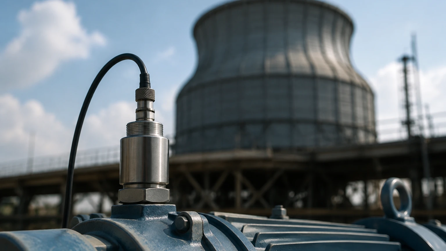
The sensor should be mounted as close to the bearing housing as possible. For cooling tower fans, sensors are typically placed on the gearbox casing (in both horizontal and vertical axes) and on the motor bearings. Alignment with the load path is essential to capture the true energy of the vibration.
Cabling and Conduit
Cables should be protected by liquid-tight flexible conduit. In cooling towers, water ingress into the sensor connector is the most common cause of failure. Using over-molded cables or hermetically sealed connectors is a best practice for long-term reliability.
Integrating Vibration and Level Monitoring
In a comprehensive cooling tower management strategy, mechanical vibration monitoring is often paired with fluid level measurement. While the cooling tower vibration sensor monitors the mechanical health of the fan and drive train, level sensors ensure that the water basin (sump) maintains the correct volume for efficient heat exchange and to prevent pump cavitation.
If the water level in the basin drops too low, the suction pumps may draw in air, leading to cavitation. This cavitation creates significant vibration that can be picked up by the mechanical sensors, potentially leading to a false diagnosis of mechanical failure when the root cause is actually a fluid level issue. For engineers looking to integrate these systems, reviewing advanced liquid level measurement options is a logical next step. You can Review product options and application support on our Main Page to see how level transmitters complement machinery health monitoring.
Common Risks and Operational Limitations
Despite their utility, vibration sensors have limitations that engineers must account for during the design phase:
* Structural Resonance: Sometimes, the cooling tower structure itself may have a natural frequency that coincides with the fan speed. This can lead to high vibration readings that do not indicate a machine fault but rather a structural design issue.
* Signal Noise: Long cable runs in industrial environments can pick up electromagnetic interference (EMI). Using shielded, twisted-pair cabling and ensuring proper grounding is vital.
* False Alarms: Sudden changes in wind load or ice buildup on fan blades (in cold climates) can cause temporary spikes in vibration. Control systems should be programmed with time delays to prevent nuisance shutdowns.
Frequently Asked Questions (FAQ)
Q: What is the recommended vibration limit for a cooling tower fan?
A: While specific limits depend on the manufacturer, ISO 10816-3 suggests that for large industrial machines, a velocity above 7.1 mm/s (0.28 ips) RMS is often considered "unrestricted" but warrants investigation, while levels exceeding 11.0 mm/s (0.43 ips) RMS may require immediate shutdown.
Q: Can I use a standard industrial accelerometer in a cooling tower?
A: Only if it is hermetically sealed and made of corrosion-resistant materials. The high-moisture environment will quickly destroy standard sensors that are not specifically rated for IP68 or higher.
Q: How often should a cooling tower vibration sensor be calibrated?
A: Annual calibration is recommended to ensure the sensitivity has not drifted due to thermal cycling or mechanical shock. Many facilities perform a "loop check" every six months to verify the signal reaches the PLC correctly.
Technical Checklist for Procurement
Before finalizing a purchase for a cooling tower vibration sensor project, confirm the following details:
1. Machine Speed: Is the fan's minimum RPM within the sensor's accurate frequency range?
2. Environment: Is the sensor housing 316L stainless steel with an IP68 rating?
3. Interface: Does the output (4-20mA or AC) match the input capabilities of your control system?
4. Cabling: Is the cable jacket material resistant to cooling tower chemicals (e.g., Teflon or Polyurethane)?
5. Mounting: Is there a flat, machined surface available on the gearbox or motor for stud mounting?
By addressing these factors, plant engineers can ensure a robust monitoring system that extends the life of their cooling assets and maintains operational efficiency.