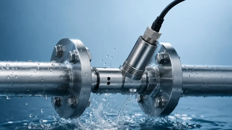
Coriolis Mass Flow Controller
Coriolis Mass Flow Controller
In the landscape of industrial process control, the Coriolis mass flow controller (MFC) represents one of the most accurate and versatile instruments for the simultaneous measurement and regulation of fluid flow. Unlike volumetric flow meters, which require compensation for temperature and pressure changes, a Coriolis mass flow controller measures the actual mass of the fluid passing through the system. This distinction is critical in high-precision industries such as chemical processing, semiconductor manufacturing, and pharmaceutical production, where the density of the medium may fluctuate during the process.
By integrating a high-precision Coriolis sensor with a control valve and advanced PID (Proportional-Integral-Derivative) electronics, these devices provide a closed-loop solution that ensures the delivered mass flow matches the desired setpoint with exceptional repeatability. This article explores the underlying physical principles, selection criteria, and engineering considerations essential for implementing Coriolis technology in modern industrial environments.
Understanding the Coriolis Measurement Principle
To effectively utilize a Coriolis mass flow controller, it is necessary to understand the physics of the Coriolis effect. The measurement sensor typically consists of one or more vibrating tubes, usually made of stainless steel or high-nickel alloys. These tubes are vibrated at their resonant frequency by an electromagnetic drive coil.
When there is no flow, the tubes vibrate uniformly. However, when a fluid (liquid or gas) enters the vibrating tube, it is forced to take on the vertical momentum of the vibration. As the fluid moves toward the point of maximum vibration amplitude, it resists being accelerated upward, pushing back against the tube. Conversely, as the fluid moves away from the center toward the exit, it resists the decrease in its vertical momentum, pushing forward. This creates a twisting effect on the tube, known as the Coriolis force.
Sensors located at the inlet and outlet sides of the tube detect this twist as a phase shift in the vibration cycle. The time delay between the two signals is directly proportional to the mass flow rate. Because mass is an intrinsic property that does not change with temperature or pressure, the Coriolis mass flow controller provides an absolute measurement. Furthermore, the frequency of the vibration changes based on the density of the fluid, allowing the device to measure density and temperature simultaneously, which can be used to calculate volumetric flow if required.
The Architecture of a Coriolis Mass Flow Controller
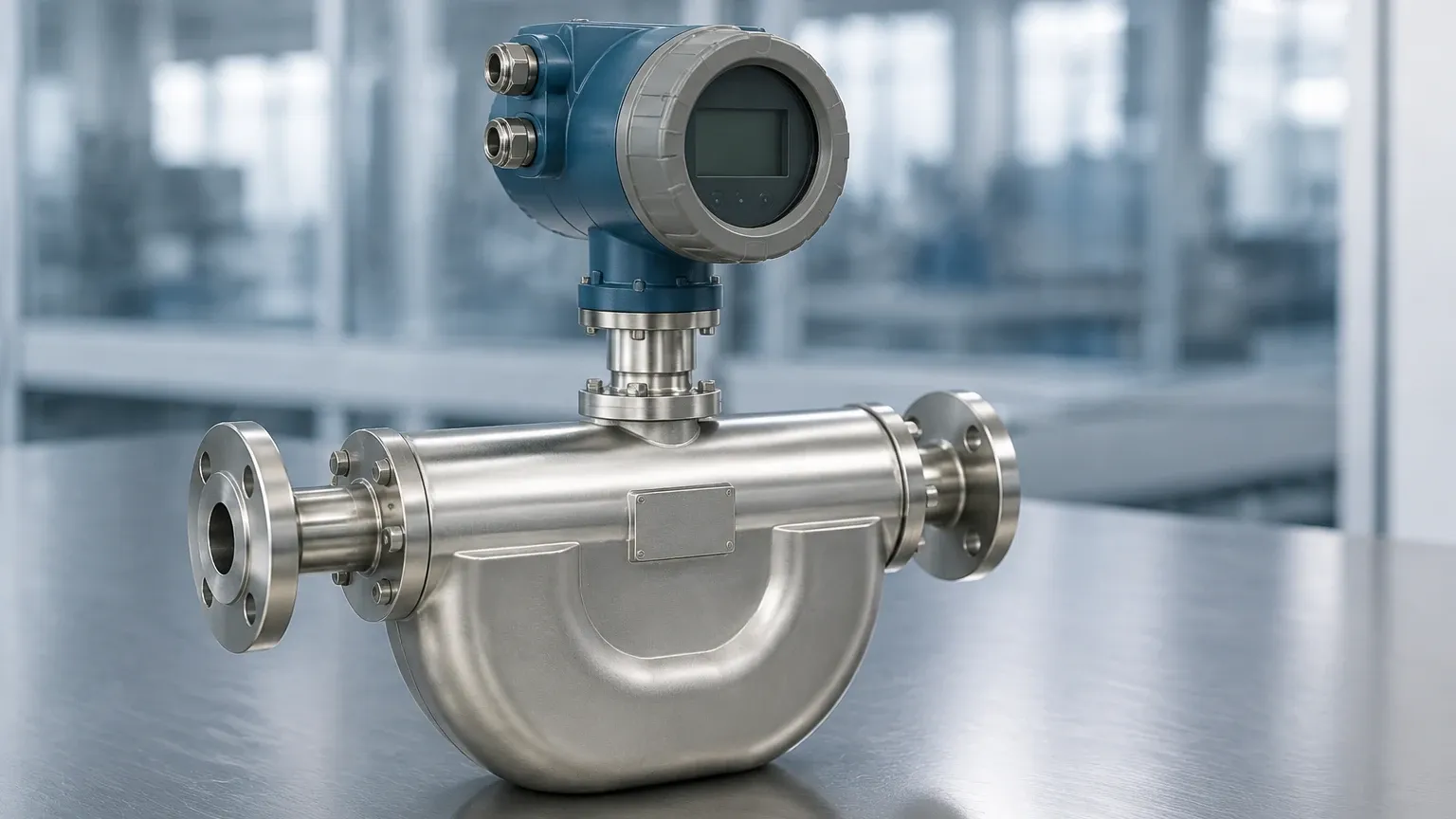
A Coriolis mass flow controller is a multi-component system housed within a single instrument body. The primary components include:
1. The Sensor: The vibrating tube assembly described above, which provides the raw mass flow data.
2. The Control Valve: Usually a solenoid-operated or motor-driven valve located downstream of the sensor. The valve modulates the flow to reach the target setpoint.
3. The Electronics (PID Controller): The microprocessor that receives the signal from the sensor, compares it to the user-defined setpoint, and calculates the necessary adjustment for the control valve.
4. Communication Interface: Modern units support various protocols such as 4-20mA, Modbus RTU, Profibus, or EtherCAT, allowing for seamless integration into a PLC or SCADA system.
This integrated approach eliminates the need for separate meters, valves, and external controllers, reducing the footprint and potential leak points in a gas or liquid delivery system.
Key Advantages in Industrial Processes
The adoption of the Coriolis mass flow controller over thermal mass flow controllers or volumetric systems is driven by several technical advantages:
* Fluid Independence: Unlike thermal MFCs, which require specific calibration factors for different gases based on their thermal properties, Coriolis controllers are largely independent of the fluid's physical properties. A unit calibrated for water can often measure a variety of chemicals without recalibration, provided the materials are compatible.
* High Accuracy: These devices typically offer accuracy levels of ±0.2% to ±0.5% of the actual mass flow rate, which is significantly better than most other flow technologies.
* Wide Turndown Ratio: Coriolis controllers can maintain accuracy over a wide range of flow rates, often exceeding 100:1, allowing a single device to handle both low-flow dosing and high-flow flushing operations.
* Multi-Parameter Output: By providing mass flow, density, and temperature, the Coriolis MFC acts as a comprehensive process analyzer.
Technical Selection Criteria and Comparison Table
Selecting the correct Coriolis mass flow controller requires a detailed analysis of the process parameters. The following table provides a reference for the typical specifications encountered in industrial applications.
| Feature | Specification Range (Typical) | Considerations |
| :— | :— | :— |
| Flow Range | 0.05 kg/h to 600 kg/h (standard units) | Higher ranges available for large-scale industrial pipes. |
| Accuracy | ±0.2% to ±0.5% of rate | Critical for high-value chemical dosing. |
| Pressure Rating | 10 bar to 100 bar (standard) | High-pressure versions available up to 400 bar. |
| Temperature Range | -50°C to +200°C | Ensure electronics are remote-mounted for high-temp. |
| Wetted Materials | 316L Stainless Steel, Hastelloy, Tantalum | Must be compatible with corrosive media. |
| Response Time | < 500 ms to 2 seconds | Faster response is needed for batching and filling. |
| Control Valve Type | Solenoid, Piezo, or Stepper Motor | Solenoid is common; Stepper is used for high pressure. |
When evaluating these specifications, engineers should also consider the "Zero Stability" of the instrument. This is the residual flow signal measured when the flow is zero. The lower the zero stability value, the more accurate the device will be at the bottom end of its flow range.
Installation and Engineering Best Practices
To achieve the high accuracy promised by Coriolis technology, proper installation is paramount. Because the measurement relies on detecting minute vibrations, external mechanical noise can interfere with the sensor.
Vibration Isolation
Coriolis mass flow controllers should be mounted on a rigid, heavy support structure. If the piping system is subject to vibration from pumps or compressors, flexible bellows or vibration-dampening mounts should be used. However, the controller itself must be securely clamped to a fixed point to ensure the internal tube vibration remains the only detectable movement.
Orientation
For liquid applications, the sensor should ideally be installed in a vertical pipe with the flow moving upward. This ensures that the tubes remain full and prevents air bubbles from becoming trapped, which would cause measurement errors. For gas applications, the controller is often mounted with the tubes pointing downward to prevent any condensed liquids from accumulating in the sensor.
Piping Requirements
One of the significant benefits of the Coriolis mass flow controller is that it does not require long straight runs of pipe before or after the meter (unlike orifice plates or ultrasonic meters). However, it is still good practice to avoid placing the controller immediately downstream of a high-turbulence source like a pressure-reducing valve.
Operational Limitations and Environmental Factors
While highly versatile, the Coriolis mass flow controller is not without limitations. Understanding these boundaries prevents premature failure and measurement drift.
1. Pressure Drop: The internal geometry of the vibrating tubes, especially in "U-shaped" designs, can cause a significant pressure drop. This must be accounted for in the system's pump or supply pressure calculations.
2. Entrained Gas/Solids: While Coriolis meters can handle some degree of multi-phase flow, excessive air bubbles in a liquid or excessive moisture in a gas can dampen the tube vibration, leading to a "stalling" of the sensor or significant inaccuracies.
3. Cost: Coriolis technology is generally more expensive than thermal or ultrasonic alternatives. The investment is typically justified by the reduction in waste (due to higher accuracy) and the elimination of the need for multiple sensors.
4. Size and Weight: Due to the internal tubes and the requirement for a robust housing, these units are often heavier and bulkier than other MFC types, which may be a factor in skid-mounted or portable equipment.
Common Applications and Use Cases
The ability to measure mass directly makes the Coriolis mass flow controller indispensable in several key areas:
* Chemical Dosing: In reactors where stoichiometric ratios are critical, measuring mass ensures that the correct number of molecules is introduced, regardless of the chemical's temperature-induced density changes.
* High-Precision Filling: In the food and beverage or pharmaceutical industries, Coriolis MFCs are used to fill containers by mass, ensuring regulatory compliance and reducing product giveaway.
* Gas Blending: For creating calibration gases or specialized atmosphere mixtures, the Coriolis MFC provides the precision needed to maintain exact concentrations.
* Supercritical Fluid Control: In processes like CO2 extraction, where the fluid exists in a state between liquid and gas, Coriolis is often the only reliable measurement method.
For engineers seeking to integrate these solutions into their existing infrastructure, it is advisable to consult detailed product catalogs. To Review product options and application support, technical teams should visit the Main Page for a comprehensive overview of available measurement technologies and customization services.
Frequently Asked Questions (FAQ)
Q: Can a Coriolis mass flow controller be used for both liquids and gases?
A: Yes. One of the primary strengths of Coriolis technology is its ability to measure any fluid that can flow through the tubes. However, the sizing of the controller and the valve orifice will differ significantly between gas and liquid applications due to density differences.
Q: Does the device require frequent recalibration?
A: Generally, no. Because the measurement is based on a physical constant (the Coriolis force), the sensor is very stable. Recalibration is usually only necessary if the wetted parts have suffered from corrosion or erosion, which would change the mass of the vibrating tubes.
Q: How does a Coriolis MFC handle pulsating flow?
A: Pulsating flow from reciprocating pumps can interfere with the tube's vibration frequency. In such cases, it is recommended to use a pulsation dampener or a longer length of flexible tubing between the pump and the controller to smooth the flow profile.
Q: Is it possible to use a Coriolis controller in hazardous areas?
A: Yes, many manufacturers offer versions with ATEX, IECEx, or FM certifications for use in explosive environments. These units typically use intrinsically safe electronics or explosion-proof housings.
In conclusion, the Coriolis mass flow controller is a sophisticated tool that solves many of the traditional challenges associated with fluid regulation. By focusing on mass rather than volume, and providing an integrated control solution, it enables higher levels of process efficiency and product quality. When selecting a unit, engineers must balance the requirements for accuracy, pressure drop, and material compatibility to ensure long-term reliability in the field. For further technical specifications and to explore a wide range of industrial measurement instruments, please refer to the Main Page.