Coriolis Mass Flow Meter Installation
Coriolis Mass Flow Meter Installation
In the realm of industrial process control, the Coriolis mass flow meter stands as one of the most accurate and versatile instruments available. Unlike volumetric flow meters, which are influenced by changes in temperature, pressure, and fluid density, Coriolis meters measure mass flow directly. This capability makes them indispensable in sectors such as chemical processing, oil and gas, and food production. However, the inherent precision of these devices is heavily dependent on correct installation practices. This guide provides a comprehensive overview of the principles, selection criteria, and technical requirements for a successful coriolis mass flow meter installation.
Understanding the Coriolis Measurement Principle
Before proceeding with installation, it is essential to understand the physics governing the device. The Coriolis effect is an inertial force first described by Gaspard-Gustave de Coriolis in the 19th century. In a flow meter, this principle is applied by using an internal drive coil to vibrate one or more flow tubes at their resonant frequency.
When a fluid (liquid or gas) enters the vibrating tubes, it is forced to take on the vertical momentum of the vibrating tube. As the fluid moves toward the point of maximum vibration, it resists being pushed upward and pushes down on the tube. Conversely, as the fluid moves away from the point of peak vibration, it resists the decrease in vertical motion and pushes up on the tube. This creates a twisting effect on the flow tubes, known as a phase shift.
Sensors located at the inlet and outlet of the tubes measure this phase shift. The time difference between the sine waves generated by these sensors is directly proportional to the mass flow rate. Simultaneously, the frequency of the vibration is used to determine the fluid density, while an internal RTD (Resistance Temperature Detector) monitors the temperature to compensate for changes in tube elasticity. Because the measurement is based on inertia, it remains largely independent of the fluid's viscosity or flow profile.
Pre-Installation Selection Criteria
Selecting the correct meter for the application is the first step in ensuring a reliable installation. Engineers must evaluate the process conditions against the meter's technical specifications. At Welk, we emphasize that the physical characteristics of the fluid and the environment dictate the meter's geometry and material.
Material Compatibility
Standard Coriolis tubes are often made from 316L stainless steel, but highly corrosive fluids may require Hastelloy, Tantalum, or Titanium. It is critical to ensure that the wetted parts are compatible with the process fluid to prevent premature failure or measurement drift.
Tube Geometry
Coriolis meters generally come in two designs: bent-tube (U-shaped) and straight-tube.
- Bent-tube meters offer a wider turndown ratio and higher sensitivity but are more prone to trapping air or sediment.
- Straight-tube meters are easier to clean (CIP/SIP) and have a lower pressure drop, making them ideal for hygienic applications or high-viscosity fluids.
Selection Reference Table
| Fluid Type | Preferred Orientation | Tube Geometry Recommendation |
| :— | :— | :— |
| Clean Liquids | Tubes Pointing Down | Bent-tube for high accuracy |
| Gases | Tubes Pointing Up | Bent-tube or Straight-tube |
| Slurries / Suspensions | Vertical (Upward Flow) | Straight-tube to prevent settling |
| Hygienic / Food Grade | Vertical (Self-draining) | Straight-tube for CIP/SIP |
| High Viscosity | Vertical or Horizontal | Straight-tube to reduce pressure drop |
Mechanical Installation Requirements
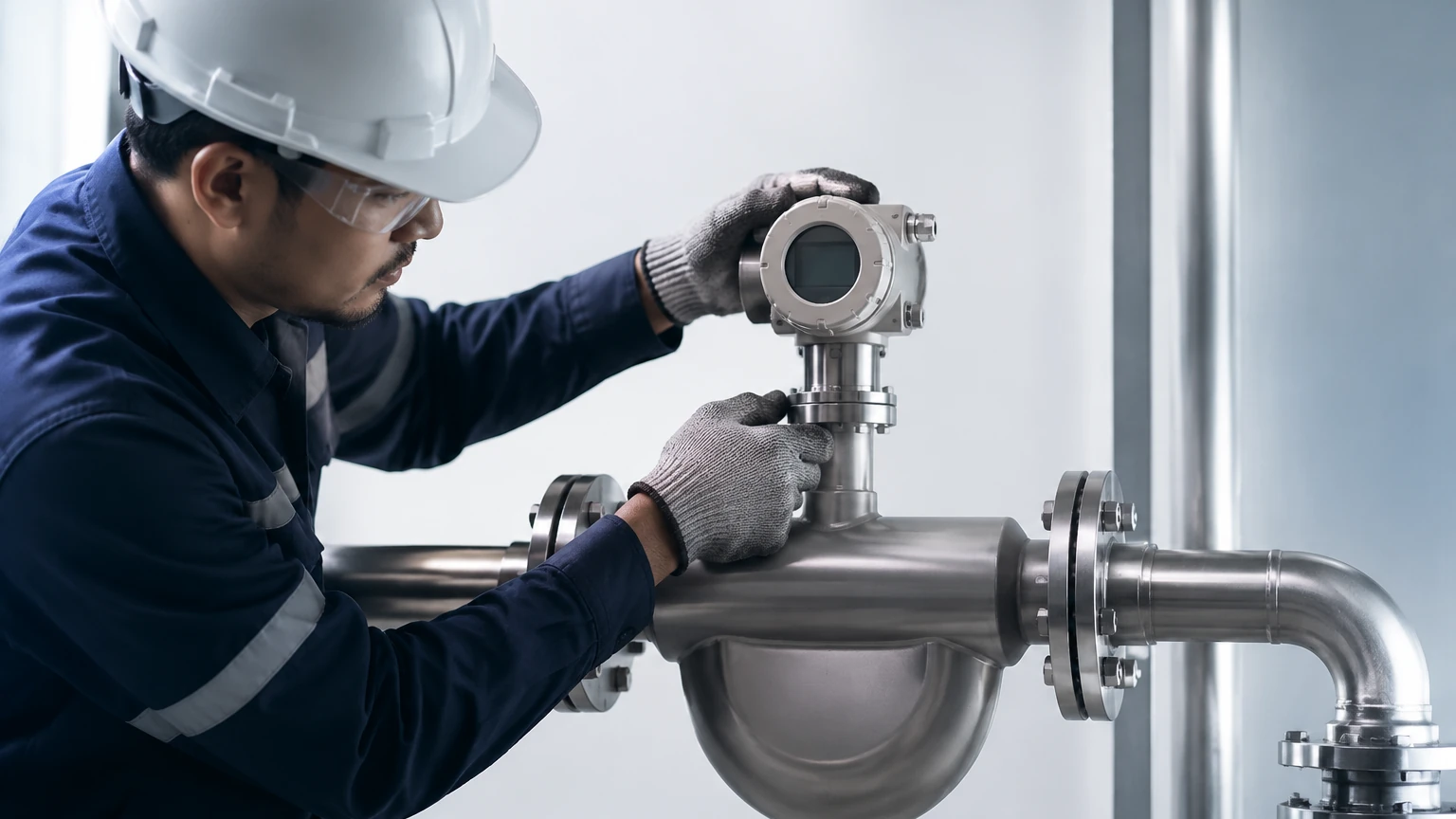
The most critical factor in a coriolis mass flow meter installation is mechanical stability. Because the meter operates by measuring micro-vibrations, any external mechanical noise or stress can significantly degrade accuracy.
Support and Mounting
Coriolis meters must be supported by the adjacent piping, not by the meter body itself. However, the piping must be rigid and securely anchored to a stable structure. For larger meters, dedicated supports should be placed within 2 to 3 pipe diameters of the inlet and outlet flanges. This prevents the weight of the meter from causing stress on the pipeline and isolates the meter from plant vibrations.
Avoiding Stress
Mechanical stress on the meter body can distort the flow tubes, leading to a "zero-point shift." During installation, ensure that the flanges are perfectly aligned. Never use the meter's flange bolts to pull a misaligned pipe into place. Thermal expansion should also be managed using expansion loops or flexible couplings elsewhere in the line, ensuring that the meter remains stress-free during temperature cycles.
Vibration Isolation
If the meter is installed near pumps, compressors, or vibrating machinery, it may experience interference. The drive frequency of the Coriolis meter is typically between 50 Hz and 1000 Hz. If external equipment operates at similar frequencies, it can cause resonance issues. In such cases, use high-quality pipe clamps and vibration-dampening mounts to isolate the measurement section.
Process Piping and Fluid Considerations
While Coriolis meters do not require the long straight pipe runs associated with magnetic or turbine meters, certain piping configurations can still impact performance.
Orientation for Liquids
For liquid applications, the meter should ideally be installed with the tubes pointing downward (the "flag" position). This ensures that the tubes remain completely full of liquid and that any entrained gas bubbles can pass through without becoming trapped in the sensor. If the meter is installed in a vertical line, the flow must always be upward to ensure the tubes remain full and to facilitate the removal of air.
Orientation for Gases
When measuring gases, the meter should be installed with the tubes pointing upward. This allows any condensed liquids (condensate) to drain out of the tubes by gravity, preventing measurement errors caused by liquid loading in a gas stream.
Avoiding Cavitation and Flashing
To maintain accuracy, the fluid must remain in a single phase. Cavitation occurs when the local pressure drops below the fluid's vapor pressure, causing bubbles to form. This is common if a control valve is placed immediately upstream of the meter. To prevent this, always install control valves downstream of the Coriolis meter. This maintains a higher back-pressure within the meter, keeping the fluid in the liquid phase.
Electrical and Signal Wiring
Modern Coriolis meters consist of a primary sensor and a secondary transmitter. The transmitter can be integrally mounted or remote-mounted.
1. Shielding: Use twisted-pair, shielded cables for signal transmission to prevent electromagnetic interference (EMI) from high-power cables or variable frequency drives (VFDs).
2. Grounding: Proper grounding is essential for safety and signal integrity. The meter body should be grounded to the process pipe, and the transmitter should have a dedicated earth ground.
3. Hazardous Areas: If the installation is in a flammable environment, ensure the meter meets the required ATEX, IECEx, or UL certifications. Use intrinsic safety barriers or explosion-proof conduits as specified by local codes.
Calibration and Zero-Point Adjustment
Once the physical installation is complete, the "Zero Calibration" is the most important commissioning step. Even a perfectly installed meter will have a slight residual offset due to the specific piping geometry and ambient conditions.
The Zeroing Procedure
1. Fill the Meter: Ensure the meter is completely full of the process fluid.
2. Establish Static Conditions: Close the downstream valve first, then the upstream valve. The fluid must be completely stationary. There must be zero flow, but the meter must remain at process pressure and temperature.
3. Stabilize: Wait for the temperature to stabilize.
4. Execute Zeroing: Initiate the zero-calibration routine via the transmitter interface. The transmitter will average the signal over a set period (usually 30 to 60 seconds) and define this as the "zero flow" point.
Failure to perform this step under actual process conditions is a leading cause of measurement inaccuracy at low flow rates.
Common Installation Risks and Troubleshooting
Despite their robustness, Coriolis meters are susceptible to specific environmental and process risks.
* Entrained Air: Even small amounts of air in a liquid stream can cause the tubes to vibrate erratically, leading to a "slug flow" error. If entrained air is unavoidable, consider using an air eliminator upstream.
* Cross-Talk: If two Coriolis meters of the same model are installed too close to each other on the same manifold, their vibrations can interfere. This is known as cross-talk. To prevent this, stagger the meters or ensure they are separated by rigid, anchored piping.
* Coating and Buildup: While Coriolis meters can handle some coating, significant buildup of paraffin, scale, or resins will change the mass of the tubes and the internal volume, affecting both density and flow measurements. Regular cleaning or the use of straight-tube designs can mitigate this.
Limitations of Coriolis Flow Meters
While highly accurate, Coriolis meters are not a universal solution for every application. Engineers should be aware of the following limitations:
1. Initial Cost: Coriolis meters are generally more expensive than vortex, electromagnetic, or ultrasonic meters. The investment must be justified by the need for mass flow accuracy or density measurement.
2. Pressure Drop: The flow path in many Coriolis meters is constricted or curved, which can result in a higher pressure drop compared to full-bore meters. This must be accounted for in pump sizing.
3. Size Constraints: Coriolis meters become very large, heavy, and expensive for pipe sizes above 300 mm (12 inches). In large-diameter water lines, other technologies may be more practical.
4. Sensitivity to Gas Fractions: While some modern meters can handle "multiphase flow," high gas volume fractions (GVF) in a liquid stream can still cause the meter to stall or lose accuracy.
Frequently Asked Questions (FAQs)
Q: Do I need straight pipe runs before and after the meter?
A: Generally, no. Coriolis meters are not sensitive to flow profile disturbances like swirls or turbulence. However, providing 3 to 5 diameters of straight pipe can help stabilize the mechanical load on the flanges.
Q: Can I install a Coriolis meter vertically?
A: Yes, vertical installation is often preferred for slurries or fluids that may outgas. However, the flow must always be in the upward direction to ensure the tubes stay full.
Q: How often should I re-zero the meter?
A: You should re-zero the meter during initial commissioning, after any major maintenance on the piping, or if the process fluid properties change significantly. In stable applications, annual verification is usually sufficient.
Q: Can Coriolis meters measure steam?
A: While they can measure high-pressure gases, Coriolis meters are rarely used for steam due to the high temperatures and velocities involved, which can exceed the mechanical limits of the vibrating tubes.
Conclusion
A successful coriolis mass flow meter installation requires a balance of mechanical precision and process understanding. By ensuring rigid support, proper orientation, and a careful zero-point calibration, users can achieve the high-accuracy measurement these instruments are designed to provide. For engineers looking to integrate these solutions into broader automation systems, reviewing the compatibility of level and flow instruments is a vital step. For more technical specifications and to explore our full range of measurement solutions, visit our Main Page. At Welk, we provide the expertise and hardware necessary to optimize industrial processes through reliable measurement technology.