Cso Flow Monitoring
Cso Flow Monitoring
Combined Sewer Overflow (CSO) flow monitoring is a critical component of modern urban wastewater management. In combined sewer systems, which collect both rainwater runoff and domestic sewage in a single pipe, heavy precipitation can exceed the capacity of the network or the treatment plant. To prevent upstream flooding, these systems are designed to overflow into nearby water bodies. Monitoring these events is essential for regulatory compliance, environmental impact assessment, and the long-term planning of hydraulic infrastructure.
For engineers and municipal operators, the challenge lies in the harsh, unpredictable environment of a sewer. CSO events are characterized by rapid changes in flow rate, high levels of debris, and potentially explosive atmospheres. Selecting the correct instrumentation requires a deep understanding of measurement principles and the specific hydraulic conditions of the monitoring site.
Measurement Principles in CSO Flow Monitoring
Before selecting hardware, it is necessary to understand how flow is calculated in open or partially filled channels, which are typical in CSO structures. Most monitoring strategies rely on one of two primary principles: the Level-to-Flow conversion or the Area-Velocity method.
Level-to-Flow Conversion (Primary Devices)
This principle is used when a hydraulic structure with known dimensions, such as a weir or a flume, is present. These structures create a predictable relationship between the liquid level (head) and the flow rate. By measuring the level at a specific point upstream of the structure, the flow can be calculated using a standardized mathematical formula.
In many CSO applications, however, installing a flume is impractical due to space constraints or the risk of sediment buildup. In these cases, engineers may use the Manning Equation to estimate flow based on level measurement within a standard pipe, though this assumes steady, uniform flow conditions which are rarely present during a storm event.
Area-Velocity (AV) Method
The Area-Velocity method calculates flow by measuring both the depth of the liquid and its mean velocity. The cross-sectional area (A) is determined from the level measurement and the known geometry of the pipe or channel. The flow (Q) is then calculated as Q = A × V. This method is preferred in locations where backwater effects occur or where the slope of the pipe is insufficient to maintain a stable level-to-flow relationship.
Core Technologies for Level and Flow Measurement
To implement the principles mentioned above, several sensor technologies are employed. Each has distinct advantages depending on the physical characteristics of the CSO chamber or outfall.
Radar Level Meters
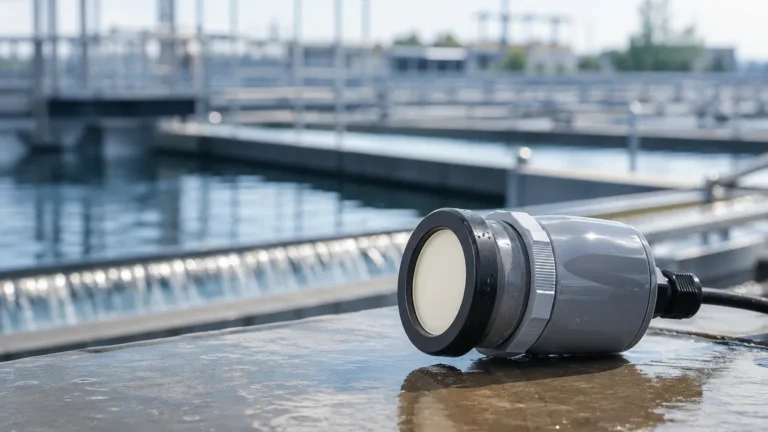
Radar technology has become the industry standard for non-contact level measurement in CSO flow monitoring. These sensors emit high-frequency microwave pulses (typically in the 26GHz or 80GHz range) that reflect off the liquid surface. The time-of-flight between emission and reception determines the distance.
Radar is particularly effective in CSO environments because it is unaffected by air temperature fluctuations, steam, or wind—factors that often compromise other technologies. For precise engineering requirements, reviewing various Main Page options for radar sensors can provide insights into beam angles and accuracy ratings necessary for narrow sewer manholes.
Ultrasonic Level Sensors
Ultrasonic sensors use sound waves to measure the distance to the water surface. While cost-effective, they are sensitive to the medium through which the sound travels. Changes in air temperature or the presence of heavy fog can alter the speed of sound, leading to measurement errors. Most modern ultrasonic units include temperature compensation, but they remain less robust than radar in the high-humidity environments typical of sewers during a discharge event.
Hydrostatic Level Transmitters
Hydrostatic sensors are contact-based devices that measure the pressure exerted by the liquid column above the sensor diaphragm. In CSO applications, these are often used as redundant backup systems. If a chamber becomes completely surcharged (full pipe flow), a non-contact sensor looking down from the ceiling will lose its signal. A submerged hydrostatic transmitter can continue to provide pressure data, allowing operators to calculate the head pressure during a full-pipe event.
Technical Selection Criteria
Choosing the right equipment for cso flow monitoring depends on the specific site geometry and the required data accuracy. The following table provides a comparison of common technologies used in these applications.
| Feature | Radar Level Meter | Ultrasonic Sensor | Hydrostatic Transmitter |
| :— | :— | :— | :— |
| Measurement Type | Non-contact | Non-contact | Contact (Submerged) |
| Accuracy | High (±2mm) | Moderate (±0.25% of range) | High (±0.1% to 0.5% span) |
| Maintenance | Low (no fouling) | Low to Moderate | High (diaphragm cleaning) |
| Environmental Impact | Minimal | Affected by vapor/wind | Affected by sediment/debris |
| Surcharge Capability | No (loses signal) | No (loses signal) | Yes (measures head pressure) |
| Typical Range | Up to 30m | Up to 15m | Up to 100m H2O |
Installation Considerations and Best Practices
Proper installation is as critical as sensor selection. Even the most accurate radar meter will provide poor data if it is poorly positioned.
1. Mounting Position: Sensors should be mounted in a location where the flow is relatively laminar (smooth). Avoid placing sensors directly above areas of high turbulence, such as the point where a side-pipe enters the main channel. For level-to-flow calculations using a weir, the sensor must be placed at a distance of at least 3 to 4 times the maximum head upstream from the weir plate.
2. Dead Zones: Every non-contact sensor has a "dead zone" (blocking distance) directly beneath the transducer face where measurements cannot be taken. Ensure the sensor is mounted high enough so that even at maximum expected flood levels, the water surface does not enter this zone.
3. Signal Beam Path: Radar and ultrasonic signals spread out in a cone. Engineers must ensure the beam path is clear of obstructions like ladders, pipe walls, or cables. An 80GHz radar is often preferred in narrow manholes because its narrow beam angle (often as small as 3 degrees) avoids these false reflections.
4. Power Constraints: Many CSO monitoring points are in remote locations without grid power. Instrumentation must be compatible with low-power DC systems (12-24V) and capable of operating with cellular data loggers that wake up periodically to transmit data.

Limitations and Operational Challenges
While technology has advanced, cso flow monitoring remains one of the most difficult applications in industrial instrumentation. Engineers must account for the following limitations:
* Foam and Surface Turbulence: Heavy rain can create foam on the surface of the wastewater. Ultrasonic signals may be absorbed by foam, while radar signals can be scattered by extreme turbulence. Signal processing algorithms (false echo suppression) are required to filter these effects.
* Debris and Ragging: Contact-based sensors, such as hydrostatic probes or submerged area-velocity sensors, are prone to "ragging." This occurs when wipes, plastic, and other debris wrap around the sensor, leading to drift or total failure.
* Regulatory Calibration: Many jurisdictions require annual calibration of CSO flow monitoring equipment. This can be difficult in active sewers. Systems that allow for remote diagnostics and verification are highly valued in these scenarios.
Frequently Asked Questions (FAQ)
Q: How do I monitor flow when the pipe is under surcharge (completely full)?
A: In surcharge conditions, standard level-to-flow equations fail because the pipe is under pressure. You must use a combination of a pressure (hydrostatic) sensor and a velocity sensor, or two pressure sensors at different points to calculate the hydraulic gradient.
Q: Can I use a radar sensor in a classified explosive area?
A: Yes. Most CSO environments are classified as Zone 0 or Zone 1 (ATEX/IECEx) due to the potential presence of methane. You must select sensors with the appropriate Intrinsic Safety (IS) or Explosion-Proof (Ex d) ratings.
Q: What is the maintenance interval for non-contact sensors in a sewer?
A: Because they do not touch the effluent, radar and ultrasonic sensors require very little maintenance. An annual visual inspection to ensure no spider webs or condensation have blocked the transducer face is usually sufficient.
Q: How do I handle data gaps during power outages?
A: Professional cso flow monitoring systems should include local data logging with internal battery backup. This ensures that even if the primary power or cellular connection fails, the event data is captured and can be retrieved later.
Conclusion
Effective cso flow monitoring is essential for protecting water quality and meeting environmental mandates. By prioritizing non-contact measurement technologies like radar and understanding the hydraulic principles of the specific site, municipalities can ensure reliable data collection even in the most demanding conditions. For those designing new monitoring stations or upgrading existing infrastructure, it is advisable to consult technical specifications on the Main Page of professional instrumentation providers to ensure the selected hardware meets the required accuracy and environmental ratings for the application.