Current Flow Meter
Current Flow Meter
In industrial process control, the term "current flow meter" typically refers to two distinct but related concepts: the measurement of fluid velocity (current) within a channel or pipe, and the use of electromagnetic induction to determine the flow rate of conductive liquids. For engineers and plant managers, selecting the correct instrumentation requires a deep understanding of the physical principles governing these measurements, as well as how flow data integrates with broader level measurement systems.
Accurate flow monitoring is essential for resource management, chemical dosing, and wastewater treatment. This guide explores the technical foundations of current flow measurement, the integration of level-sensing technology in flow calculations, and the criteria for selecting the appropriate instrument for specific industrial environments.
Measurement Principles of Current Flow Meters
To effectively implement a flow measurement solution, one must first categorize the application based on whether the fluid is in a closed pipe or an open channel. The principles of operation vary significantly between these two scenarios.
Electromagnetic Induction (Magmeters)
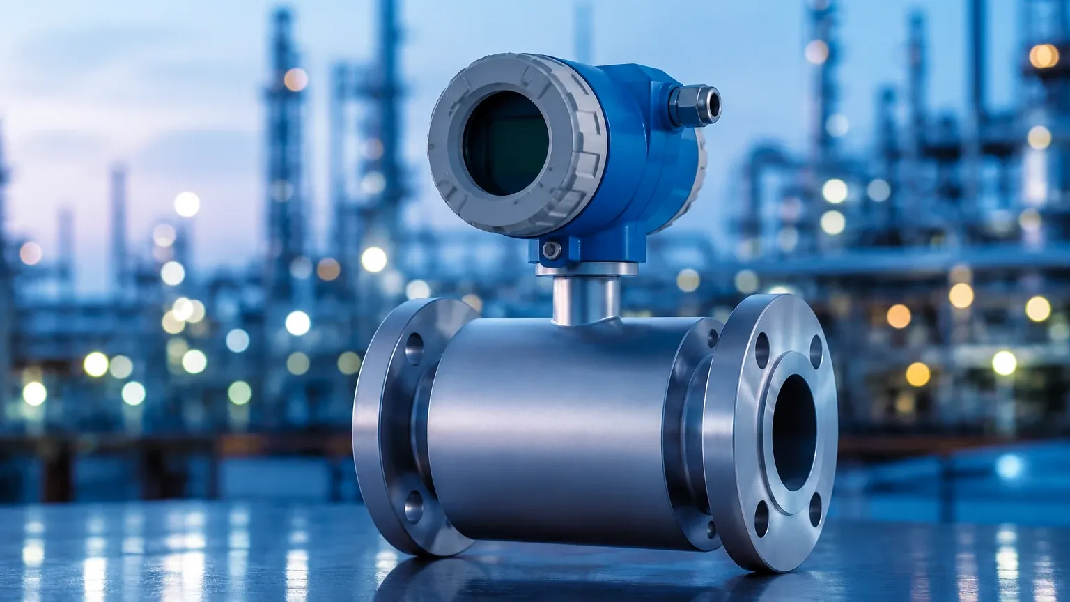
The most common industrial "current" flow meter for closed-loop systems is the electromagnetic flow meter, or magmeter. This device operates based on Faraday’s Law of Electromagnetic Induction. The law states that a voltage is induced when a conductive medium passes through a magnetic field.
In a magmeter, two field coils located inside the meter body generate a magnetic field perpendicular to the flow direction. As a conductive liquid (such as water, acids, or slurries) flows through this field, it acts as a moving conductor, inducing a voltage. This voltage is captured by electrodes mounted on the pipe walls. The induced voltage ($E$) is directly proportional to the average flow velocity ($v$), the magnetic field strength ($B$), and the distance between the electrodes ($d$):
$$E = B \cdot v \cdot d$$
Because $B$ and $d$ are constant parameters of the meter, the voltage is a linear representation of the fluid velocity. By multiplying this velocity by the cross-sectional area of the pipe, the meter calculates the volumetric flow rate.
Open Channel Flow (Level-to-Flow Conversion)
In many environmental and water treatment applications, fluid flows through open channels, flumes, or weirs rather than pressurized pipes. In these cases, a "current flow meter" often refers to a system that combines a level measurement instrument with a primary device (like a Parshall flume).
This method relies on the principle that for a specific channel geometry, there is a known mathematical relationship between the liquid level (head) and the flow rate. By using high-precision radar or ultrasonic level sensors, the system determines the height of the liquid and applies a discharge equation to calculate the flow. This is a critical area where industrial level measurement expertise intersects with flow monitoring. For more information on the sensors used in these applications, you may visit the Main Page of specialized instrument manufacturers.
Acoustic Doppler Current Profilers (ADCP)
For large-scale water velocity measurements in rivers or large conduits, Acoustic Doppler technology is employed. These meters emit ultrasonic pulses that reflect off particles or bubbles in the water. By measuring the frequency shift (the Doppler effect) of the returned signal, the instrument determines the velocity of the water current. This is particularly useful for non-conductive fluids or very large open-water bodies where electromagnetic meters are impractical.
Key Evaluation Criteria for Selection
Choosing a current flow meter requires an analysis of the fluid properties and the physical constraints of the installation site. The following table provides a comparison of common technologies used in industrial flow and level-related flow measurement.
Technology Comparison Table
| Feature | Electromagnetic Flow Meter | Ultrasonic (Open Channel) | Radar (Open Channel) | Hydrostatic (Level-based) |
| :— | :— | :— | :— | :— |
| Fluid Type | Conductive liquids (>5 μS/cm) | Any liquid (non-contact) | Any liquid (non-contact) | Clean or slightly dirty liquids |
| Accuracy | ±0.5% of rate | ±1% to ±5% of flow | ±0.5% to ±2% of flow | ±0.1% to ±0.5% of span |
| Pipe/Channel | Closed pipe (full) | Open channel / Flume | Open channel / Flume | Tanks / Vents |
| Maintenance | Low (no moving parts) | Low (non-contact) | Very Low (non-contact) | Moderate (contacting) |
| Pressure Drop | Zero | N/A | N/A | N/A |
| Common Use | Chemical, Water, Food | Wastewater, Irrigation | Harsh chemicals, Sludge | Deep wells, Reservoirs |
Practical Selection and Application Engineering
Fluid Conductivity
For electromagnetic current flow meters, the fluid must have a minimum conductivity, typically 5 μS/cm or higher. This makes magmeters unsuitable for deionized water, oils, or hydrocarbons. In such instances, ultrasonic or radar-based level sensors used in conjunction with flow structures are preferred.
Pipe Configuration
Magmeters require the pipe to be completely full to provide an accurate reading. If the pipe is partially full, the meter will over-calculate the flow rate because it assumes the entire cross-sectional area is occupied by the fluid. If a full pipe cannot be guaranteed, engineers should opt for an open-channel flow configuration using a level transmitter.
Signal Integration
Most modern current flow meters provide a 4-20mA analog output, often referred to as a "current loop." This signal is proportional to the flow rate and is easily integrated into PLC (Programmable Logic Controller) or SCADA systems. Digital protocols such as Modbus RS485 or HART are also standard for transmitting diagnostic data alongside the flow measurement.
Installation Considerations
Proper installation is the most significant factor in ensuring the long-term reliability of a current flow meter. Even the most advanced sensor will fail to provide accurate data if hydraulic conditions are ignored.
1. Straight Run Requirements: To ensure a stable velocity profile, meters typically require a straight run of pipe upstream (usually 5 to 10 times the pipe diameter) and downstream (2 to 5 times the diameter). This minimizes turbulence caused by elbows, valves, or pumps.
2. Grounding: Electromagnetic meters are highly sensitive to electrical noise. Proper grounding of the fluid to the meter body is essential, especially in lined pipes or plastic piping systems. Grounding rings are often required to provide a path for stray currents.
3. Orientation: In closed pipes, the meter should be installed in a vertical position with the flow moving upward. This ensures the pipe remains full and prevents the accumulation of air bubbles at the electrodes. If horizontal installation is necessary, the electrode axis must be horizontal to avoid interference from air (at the top) or sediment (at the bottom).
4. Environmental Protection: For open-channel applications, sensors must be rated for the environment. Ultrasonic sensors can be affected by heavy foam or steam, whereas radar level sensors are immune to these surface conditions, making them more reliable for high-accuracy flow calculation in challenging industrial basins.
Common Risks and Limitations
While current flow meters are robust, certain conditions can compromise their performance:
* Entrained Air: Air bubbles in a liquid stream can cause significant measurement errors in both electromagnetic and ultrasonic meters. In magmeters, air acts as a non-conductive void, while in ultrasonic systems, it scatters the signal.
* Scaling and Coating: In wastewater or chemical processing, material can build up on the electrodes or the sensor face. This "coating" can insulate electrodes in magmeters or attenuate the signal in ultrasonic level sensors. Selecting a meter with "empty pipe detection" or self-cleaning electrodes can mitigate these risks.
* Lining Vacuum: In high-temperature or vacuum applications, the internal liner of a magmeter (often PTFE or PFA) can collapse if not properly specified. Mechanical reinforcement of the liner is necessary for these specific process conditions.
Information Confirmation for Project Planning
Before finalizing the procurement of a current flow meter, project teams should confirm the following technical details:
* Minimum and Maximum Flow Rates: Ensure the meter's "turn-down ratio" covers the entire range of expected flow, including seasonal variations in water treatment or batch processing peaks.
* Chemical Compatibility: Verify that the wetted materials (liners and electrodes) are resistant to the process fluid. For example, Hastelloy C electrodes are often required for aggressive acids, while EPDM or Neoprene liners are suitable for standard water applications.
* Power Supply and Output: Confirm whether the site provides 24V DC or 110/220V AC power and whether the control system requires 4-20mA, pulse, or digital communication.
* Regulatory Compliance: For custody transfer or environmental discharge reporting, ensure the meter meets local standards (such as MCERTS, OIML, or NIST traceability).
Frequently Asked Questions (FAQ)
Q: Can a current flow meter measure the flow of oil?
A: Standard electromagnetic flow meters cannot measure oil because it is non-conductive. For oil flow, one should use ultrasonic (transit-time), turbine, or Coriolis meters. Alternatively, if the oil is in a tank or open channel, level-based flow measurement can be used.
Q: What is the difference between a flow meter and a current meter?
A: In common industrial parlance, a flow meter measures the total volume of fluid passing a point per unit of time (e.g., m³/h). A current meter often refers specifically to measuring the velocity of the fluid at a specific point (e.g., m/s), though the terms are frequently used interchangeably in water management.
Q: How often should a flow meter be calibrated?
A: Calibration frequency depends on the criticality of the measurement and the nature of the fluid. For most industrial applications, an annual calibration check is recommended. Systems measuring abrasive slurries or corrosive chemicals may require more frequent verification.
Q: How does temperature affect the measurement?
A: Electromagnetic meters are relatively insensitive to temperature changes, provided the temperature remains within the limits of the liner material. However, for level-based flow measurement using ultrasonic sensors, temperature compensation is vital because the speed of sound changes with air temperature.
By integrating reliable level measurement technologies with robust flow principles, industrial facilities can achieve precise control over their liquid processes. Whether through direct electromagnetic induction in closed pipes or sophisticated level-to-flow conversions in open channels, the modern current flow meter remains a cornerstone of industrial automation and environmental stewardship.