Dielectirc Constant
Dielectirc Constant
In the field of industrial process control, the dielectric constant (often referred to as relative permittivity) is perhaps the most critical physical property when selecting and calibrating level measurement instruments. Whether an engineer is deploying a high-frequency radar, a guided wave radar (GWR), or a capacitance-based sensor, the dielectric constant of the medium determines the strength of the reflected signal and the overall accuracy of the measurement. Understanding the nuances of the dielectirc constant is essential for ensuring reliable data in applications ranging from simple water storage to complex chemical reactors.
This guide provides a technical overview of how dielectric properties influence level measurement, the principles behind electromagnetic wave propagation, and practical considerations for instrument selection across various industrial media.
Measurement Principles and the Dielectric Constant
To understand why the dielectirc constant is so vital, one must first look at the physics of electromagnetic (EM) wave propagation. The dielectric constant ($ε_r$) is a dimensionless ratio that compares the permittivity of a substance to the permittivity of a vacuum. In a vacuum, the dielectric constant is exactly 1.0. Air is very close to this, at approximately 1.0006.
Wave Velocity and Reflection
When a radar level meter emits a pulse of microwave energy, the speed at which that pulse travels through the headspace of a tank is determined by the medium (usually air or nitrogen). However, the amount of energy reflected back to the sensor at the product surface depends on the change in the dielectric constant between the gas phase and the liquid/solid phase.
According to Fresnel’s equations, the reflection coefficient ($R$) is calculated based on the difference in the square roots of the dielectric constants of the two media. A larger difference in $ε_r$ results in a stronger reflected signal. For instance, water has a high dielectric constant (approximately 80 at 20°C), making it an excellent reflector for radar signals. Conversely, hydrocarbons like diesel or hexane have low dielectric constants (typically 1.9 to 2.1), which reflect a much smaller portion of the energy, allowing the rest to penetrate the liquid.
Capacitance and Charge Storage
In capacitance level measurement, the dielectric constant plays a different but equally fundamental role. A capacitance probe and the tank wall (or a reference rod) act as the two plates of a capacitor. The material being measured acts as the dielectric medium. The capacitance ($C$) is directly proportional to the dielectric constant of the material between the plates:
$$C = ε_0 ε_r (A/d)$$
Where:
* $ε_0$ is the permittivity of free space.
* $ε_r$ is the dielectric constant of the material.
* $A$ is the area of the plates.
* $d$ is the distance between the plates.
As the level of the material rises, it replaces air (low $ε_r$) with the process medium (higher $ε_r$), causing a measurable change in capacitance that is converted into a level reading.
Impact on Radar Level Meters
Radar level measurement is generally divided into two categories: non-contact (free-space) radar and contact (guided wave) radar. Both are heavily influenced by the dielectirc constant of the target material.
Non-Contact Radar
Non-contact radar units, such as 26GHz or 80GHz transmitters, depend entirely on the "echo" from the surface. If the dielectric constant is too low (typically below 1.4), the reflection may be too weak for the sensor to distinguish from background noise or the tank bottom. In such cases, the microwave energy simply passes through the medium, hits the bottom of the vessel, and returns an incorrect "empty" reading even if the tank is full.
Guided Wave Radar (GWR)
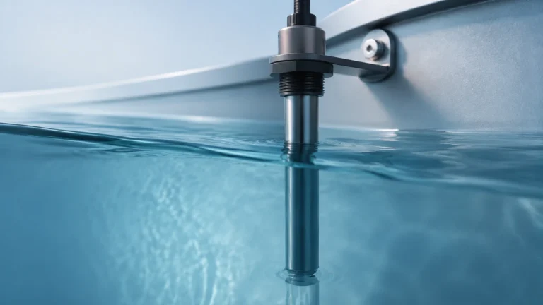
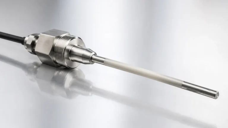
Guided wave radar uses a physical probe (cable or rod) to guide the microwave pulse to the surface. This technology is more efficient for low dielectric materials because the energy is concentrated around the probe rather than spreading out through the tank. GWR can often measure materials with a dielectirc constant as low as 1.2. Furthermore, GWR is the preferred technology for interface measurement—calculating the level of two different liquids in the same tank, such as oil over water.
Material Reference Table
When selecting an instrument, engineers should refer to the dielectric constant of the specific media. The following table lists common industrial materials and their typical $ε_r$ values at room temperature (20°C / 68°F).
| Material | Dielectric Constant ($ε_r$) | Measurement Ease |
| :— | :— | :— |
| Vacuum | 1.0 | N/A |
| Air | 1.0 | N/A |
| Plastic Pellets (PE/PP) | 1.1 – 1.5 | Difficult (Requires GWR or High-Gain Radar) |
| Diesel / Fuel Oil | 2.1 | Moderate |
| Benzene | 2.3 | Moderate |
| Canola Oil | 2.4 | Moderate |
| Grain (Corn/Wheat) | 3.0 – 5.0 | Easy |
| Sand | 3.0 – 5.0 | Easy |
| Alcohol (Ethanol) | 24.0 | Very Easy |
| Glycol | 37.0 | Very Easy |
| Water | 80.0 | Excellent |
| Sulfuric Acid | 84.0 | Excellent |
*Note: These values are approximate. Factors such as temperature, moisture content in solids, and chemical purity can alter the actual dielectirc constant.*
Practical Selection Criteria
Choosing the right level meter requires matching the instrument's sensitivity to the material's dielectric properties. On the Main Page of our technical resource, you can find detailed specifications for various sensor types tailored to these properties.
1. High Dielectric (> 10): Almost any radar or ultrasonic sensor will work. Reflection is strong, and signal-to-noise ratios are high. Standard non-contact radar is often the most cost-effective choice.
2. Medium Dielectric (3 to 10): Non-contact radar works well, but care must be taken if there is heavy foam or turbulence, which can scatter the signal. GWR is a robust alternative.
3. Low Dielectric (1.4 to 3): This range includes most hydrocarbons and solvents. High-frequency 80GHz radar or GWR with a coaxial probe is recommended to maximize signal reflection.
4. Very Low Dielectric (< 1.4): These materials (like liquefied gases or specialized powders) are challenging. A coaxial GWR probe or a capacitance probe with a high-sensitivity pre-amplifier is typically required.

Installation and Engineering Considerations
Even with the correct sensor, the physical installation can affect how the dielectirc constant influences the reading.
Signal Attenuation and Foam
Foam on the surface of a liquid can have a very different dielectric constant than the liquid itself. If the foam is dense and contains a high moisture content, it may reflect the radar signal prematurely, leading to a false high reading. If the foam is "dry" (mostly air), the radar signal may pass through it, but lose energy in the process (attenuation). For applications with heavy foam, GWR or hydrostatic pressure transmitters are often more reliable than non-contact radar.
Turbulence and Surface Conditions
A turbulent surface increases the scattering of the radar signal. For low dielectric liquids, this scattering can result in a total loss of signal. In these scenarios, installing the sensor inside a stilling well or a bypass chamber (side-mounted) is standard practice. The stilling well acts as a waveguide, ensuring that the microwave energy is directed straight to the surface and back, regardless of the dielectirc constant or surface ripples.
Interface Measurement
In interface applications, the top liquid must have a lower dielectric constant than the bottom liquid. Typically, there must be a difference of at least 10 in their dielectric values for a Guided Wave Radar to accurately detect the transition point. The upper layer must also be non-conductive. As the pulse travels through the upper layer (e.g., oil), its speed is reduced by the dielectirc constant of that oil, which the transmitter must account for to accurately calculate the distance to the water interface.
Limitations and Troubleshooting
While the dielectirc constant is a reliable metric, it is not static. Engineers should be aware of the following limitations:
* Temperature Sensitivity: For many liquids, the dielectric constant decreases as temperature increases. If a process operates at extreme temperatures (e.g., > 200°C), the $ε_r$ may drop enough to affect signal strength.
* Moisture in Solids: In bulk solids like grain or sand, a small increase in moisture content can significantly raise the dielectirc constant. This usually makes radar measurement easier but can affect the calibration of capacitance probes.
* Coating and Build-up: If a high-dielectric material (like a water-based slurry) coats a GWR probe or a non-contact radar lens, the sensor may "see" the coating instead of the actual level. Using PTFE-coated probes or air purging for non-contact lenses can mitigate this.
Frequently Asked Questions (FAQs)
Q: Can I measure the level of a material if I don't know its dielectric constant?
A: Yes, for non-contact radar, as long as the material is reflective enough to provide an echo. However, for capacitance meters and interface measurements with GWR, the dielectirc constant must be known and programmed into the device for accuracy.
Q: What is the minimum dielectric constant for standard radar?
A: Most modern industrial radars can handle materials down to $ε_r = 1.4$. Some high-performance 80GHz units can go as low as 1.2 with specialized software algorithms.
Q: Does the dielectric constant affect ultrasonic level sensors?
A: No. Ultrasonic sensors use sound waves, which reflect based on the density difference between the air and the material. The dielectirc constant is irrelevant to ultrasonic technology, though ultrasonics have their own limitations regarding vacuum, dust, and temperature vapors.
Q: Why is my GWR showing a lower level than actual in an oil/water interface?
A: This is often due to the "dielectric offset." The radar pulse travels slower through the upper oil layer than through air. If the transmitter is not correctly programmed with the dielectirc constant of the upper layer, it will miscalculate the distance to the interface.
Conclusion
The dielectirc constant is the cornerstone of electromagnetic level measurement. By understanding how this property affects signal reflection and wave velocity, engineers can avoid common pitfalls such as signal loss in low-dielectric fluids or inaccuracies in interface applications. When selecting equipment, always verify the minimum dielectric requirements of the sensor against the lowest possible $ε_r$ of your process media under operating conditions. For more detailed technical specifications and product selection tools, visit the Main Page to explore our range of industrial level measurement solutions.