Differential Flow Measurement
Differential Flow Measurement
Differential flow measurement remains the most widely utilized method for quantifying fluid movement in industrial processes. Despite the emergence of ultrasonic and electromagnetic technologies, the reliability, simplicity, and well-understood physics of differential pressure (DP) systems ensure their continued dominance in sectors ranging from water treatment to oil and gas. This guide provides a technical overview of the principles, hardware configurations, and engineering considerations essential for selecting and maintaining these systems.
The Physics of Differential Pressure
The fundamental principle underlying differential flow measurement is Bernoulli’s Equation, which describes the relationship between the velocity of a fluid and its pressure. When a fluid flowing through a pipe encounters a physical restriction (a primary element), its velocity increases at the point of restriction. According to the principle of conservation of energy, this increase in kinetic energy must be accompanied by a corresponding decrease in static pressure.
By measuring the pressure upstream of the restriction ($P_1$) and the pressure at or immediately downstream of the restriction ($P_2$), the differential pressure ($ΔP = P_1 – P_2$) can be determined. The flow rate ($Q$) is proportional to the square root of this differential pressure:
$$Q = k \cdot \sqrt{\Delta P}$$
Where $k$ is a constant factor derived from the pipe diameter, the bore size of the restriction, and the physical properties of the fluid (such as density and viscosity). Because the relationship is non-linear, the accuracy of differential flow measurement is typically highest at the upper end of the instrument's range.
Primary Elements for Differential Flow Measurement
The "primary element" is the hardware component that creates the pressure drop. The choice of element depends on the fluid type, required accuracy, and the allowable permanent pressure loss in the system.
Orifice Plates
An orifice plate is a thin metal disk with a precision-machined hole, typically centered (concentric). It is the most common primary element due to its low cost and ease of installation between standard pipe flanges. However, it creates a significant permanent pressure loss and is susceptible to wear or debris accumulation at the sharp edge of the bore.
Venturi Tubes
A Venturi tube consists of a converging conical section, a cylindrical throat, and a diverging recovery section. It is designed to minimize turbulence and maximize pressure recovery. While more expensive and larger than orifice plates, Venturi tubes are ideal for applications where low pressure loss is critical or when measuring slurries and dirty fluids, as their smooth internal profile prevents sediment buildup.
Flow Nozzles
Flow nozzles are essentially a hybrid between an orifice plate and a Venturi tube. They feature a curved inlet that leads to a short cylindrical throat. They are particularly effective for high-velocity flows and are frequently used in high-temperature steam applications due to their structural rigidity and erosion resistance.
Pitot Tubes and Averaging Pitot Tubes
Unlike the previous elements that restrict the entire flow stream, Pitot tubes measure the difference between static pressure and impact (total) pressure at a specific point. Averaging Pitot tubes use multiple sensing ports across the pipe diameter to provide a more representative flow profile. These are favored for large ductwork and gas flows where minimal pressure drop is required.
Integration with Level Measurement Systems
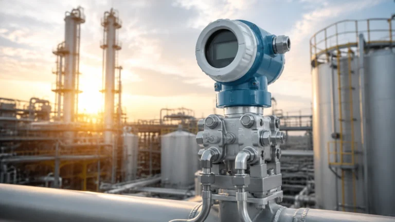
In many industrial environments, the technology used for differential flow measurement is intrinsically linked to level measurement. Differential pressure transmitters are versatile instruments; the same sensor used to calculate flow across an orifice plate can be used to measure the hydrostatic head in a pressurized vessel to determine liquid level.
For engineers managing complex process plants, standardizing on DP technology across both flow and level applications can simplify spare parts inventory and technician training. When designing these systems, it is often beneficial to consult comprehensive technical resources. For instance, reviewing product options and application support on the Main Page of an industrial instrument manufacturer can help identify high-precision transmitters capable of handling both flow and level duties in harsh environments.
Technical Selection Criteria
Choosing the correct primary element requires an evaluation of the process conditions and the physical properties of the media. The following table summarizes the performance characteristics of standard differential flow measurement elements.
Selection Comparison Table
| Element Type | Typical Accuracy | Permanent Pressure Loss | Suitable Fluids | Relative Cost |
| :— | :— | :— | :— | :— |
| Orifice Plate | ±1% to ±3% | High (60-80% of ±P) | Clean liquids/gases | Low |
| Venturi Tube | ±0.5% to ±1.5% | Low (10-20% of ±P) | Slurries, high-flow | High |
| Flow Nozzle | ±1% to ±2% | Medium (40-60% of ±P) | Steam, high-velocity | Medium |
| Pitot Tube | ±1% to ±5% | Very Low (≤5% of ±P) | Large volume gas | Low/Medium |
Key Evaluation Factors
1. Reynolds Number ($Re$): Most DP meters require a minimum Reynolds number (typically $>10,000$) to maintain a predictable discharge coefficient. If the flow is laminar or transitional, accuracy will degrade significantly.
2. Turndown Ratio: Standard DP systems typically offer a 3:1 or 4:1 turndown ratio. If the process requires measuring flow across a wider range (e.g., 10:1), stacked transmitters or alternative technologies may be necessary.
3. Fluid State: Ensure the fluid remains in a single phase. The presence of gas bubbles in a liquid line or liquid droplets in a gas line will cause erratic differential pressure readings.

Installation and Engineering Best Practices
The performance of a differential flow measurement system is heavily dependent on the quality of the installation. Even the most precise transmitter cannot compensate for poor hydraulic conditions.
Straight Pipe Requirements
To ensure a fully developed flow profile, primary elements must be installed with specific lengths of straight pipe both upstream and downstream. A common engineering rule of thumb is "10D upstream and 5D downstream" (where D is the pipe diameter), though specific configurations like elbows or valves may require up to 40D of straight pipe. Flow conditioners can be used to reduce these requirements in space-constrained installations.
Impulse Line Routing
Impulse lines (the small-bore tubing connecting the pipe to the transmitter) must be installed correctly to prevent measurement errors:
* Liquid Service: The transmitter should be mounted below the pipe tapping to allow gas bubbles to rise back into the process line.
* Gas Service: The transmitter should be mounted above the pipe tapping to allow any condensate to drain back into the process line.
* Slope: Impulse lines should always be sloped (at least 1:12) to prevent the trapping of air or liquid.
Manifold Use
A 3-way or 5-way valve manifold should always be installed between the process and the transmitter. This allows for safe isolation, venting, and zero-point calibration without removing the instrument from the process line.
Limitations and Operational Risks
While robust, differential flow measurement is subject to specific limitations that must be managed through proactive maintenance and design:
* Square Root Sensitivity: At the lower 10% of the flow range, the differential pressure produced is only 1% of the full-scale DP. This makes the system highly sensitive to small zero-shifts or noise at low flow rates.
* Permanent Pressure Loss: The energy lost to friction and turbulence across an orifice plate can result in increased pumping costs over the life of the plant. In high-volume systems, the higher capital cost of a Venturi tube is often offset by energy savings within 12 to 24 months.
* Clogging and Erosion: In abrasive services, the sharp edge of an orifice plate can round off over time, leading to a consistent under-measurement of flow. Similarly, impulse lines can plug in viscous or slurry applications, requiring regular purging or the use of diaphragm seals.
Frequently Asked Questions (FAQ)
Q: How often should a DP flow meter be calibrated?
A: While the transmitter electronics are highly stable, the primary element (like an orifice plate) should be inspected annually for erosion or buildup. The transmitter itself should undergo a zero-check every 6 to 12 months.
Q: Can differential flow measurement be used for steam?
A: Yes, it is one of the most common methods for steam. However, it requires "condensation pots" in the impulse lines to ensure the transmitter diaphragms are protected by a constant head of water (condensate) rather than direct contact with live steam.
Q: What happens if the orifice plate is installed backward?
A: Most orifice plates are beveled on the downstream side. If installed backward, the flow profile is disrupted incorrectly, typically resulting in a significant under-reading of the actual flow rate (often by 10-15%).
Conclusion
Differential flow measurement remains a foundational technology in modern process control due to its versatility and the extensive body of empirical data supporting its use. By understanding the relationship between fluid velocity and pressure drop, and by adhering to strict installation standards regarding straight pipe runs and impulse line routing, engineers can achieve highly reliable results. For those integrating flow data with broader tank and vessel management systems, utilizing high-quality instrumentation—such as the solutions found on the Main Page of industry specialists—ensures that both flow and level measurements contribute to a safe and efficient operational environment.