Float Liquid Level Sensor
Float Liquid Level Sensor
In the landscape of industrial automation and process control, the float liquid level sensor remains one of the most reliable and widely implemented technologies for monitoring fluid volumes. Despite the emergence of non-contact technologies like radar and ultrasonic sensors, float-based systems are favored for their simplicity, cost-effectiveness, and inherent accuracy in specific physical conditions. As a professional manufacturer, Welk provides a range of these instruments designed to meet the rigorous demands of water treatment, chemical processing, and the oil and gas sectors.
Understanding the mechanical and electrical foundations of these sensors is essential for engineers and procurement specialists aiming to optimize their liquid management systems. This guide explores the principles, types, selection criteria, and installation requirements for float liquid level sensors.
Measurement Principles of Float Liquid Level Sensors
The operation of a float liquid level sensor is governed by Archimedes' Principle of Buoyancy. The principle states that any object, wholly or partially immersed in a fluid, is buoyed up by a force equal to the weight of the fluid displaced by the object.
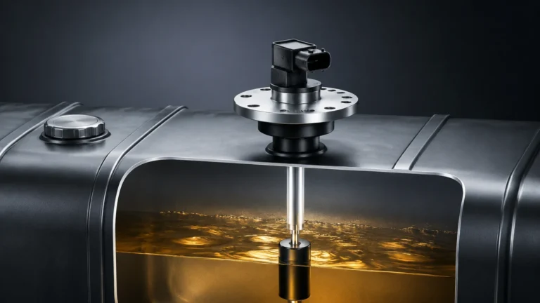
In a practical sensing application, a float—typically a hollow sphere or cylinder—is designed with a lower density than the process liquid. As the liquid level rises or falls, the float moves vertically along a guide tube or pivots on an arm. This mechanical movement is then converted into an electrical signal through various methods:
1. Magnetic Coupling: The float contains an internal permanent magnet. Inside the stationary guide tube (stem) are one or more hermetically sealed reed switches or a continuous sensing element. As the float passes these points, the magnetic field actuates the switches or alters the resistance of a circuit.
2. Mechanical Linkage: In older or heavy-duty industrial designs, the float is connected to a rod or cable that physically moves a pointer on a scale or triggers a microswitch outside the tank.
3. Magnetostriction: For high-precision continuous measurement, a magnetostrictive wire is housed within the stem. The interaction between the float's magnetic field and an electrical pulse sent down the wire creates a torsional strain wave. By measuring the time it takes for this wave to return, the sensor determines the exact position of the float with sub-millimeter accuracy.
By utilizing these principles, float sensors provide either "point level" detection (triggering at specific high or low marks) or "continuous level" measurement (providing a 4-20mA or digital output proportional to the total volume).
Types of Float Liquid Level Sensors
Selecting the correct sensor requires an understanding of the different configurations available. Each type is suited to specific tank geometries and environmental conditions.
Single and Multi-Point Float Switches
These are used primarily for alarm functions or pump control. A single-point switch might be used to prevent a tank from overflowing, while a multi-point switch can manage high-level alarms, low-level alarms, and pump-start/stop cycles within a single installation. These are highly robust and require no external power to operate the reed switch itself.
Continuous Float Transmitters
For applications requiring real-time monitoring of tank levels, continuous transmitters are used. These sensors typically feature a series of reed switches and resistors spaced at intervals (e.g., 5mm, 10mm, or 20mm) along the stem. The resolution is determined by the spacing of these components. For even higher precision, magnetostrictive float sensors are utilized, often found in fuel custody transfer or high-value chemical storage.
Side-Mounted (Horizontal) Float Switches
When top access to a tank is restricted, side-mounted switches are installed through the tank wall. These usually operate on a hinge mechanism. When the liquid reaches the float, it rises and tilts a lever that actuates a microswitch or moves a magnet toward a reed switch. These are common in small vessels and hydraulic power units.
Cable-Suspended Float Switches
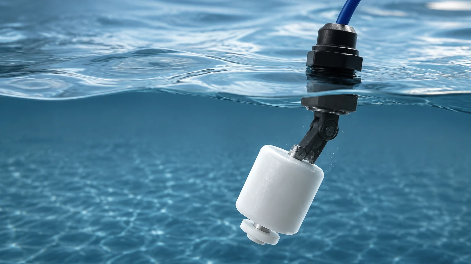
Commonly used in wastewater sumps and large open reservoirs, these sensors consist of a float tethered by a flexible cable. As the water level rises, the float tilts, causing an internal ball to roll and activate a switch. Their primary advantage is the ability to handle large level fluctuations (several meters) without needing a long, rigid stem.
Practical Selection Criteria
To ensure the longevity and accuracy of a float liquid level sensor, engineers must evaluate several environmental and chemical factors. For comprehensive technical specifications, professionals often Review product options and application support to match the sensor to their specific process.
1. Media Density (Specific Gravity)
For a float to function, its density must be significantly lower than that of the liquid. Most industrial floats are designed for liquids with a specific gravity (SG) of 0.8 or higher. If the liquid is a light hydrocarbon with an SG of 0.6, a specialized high-buoyancy float (often made of thin-walled titanium or stainless steel) is required.
2. Chemical Compatibility
The material of the float and the stem must resist corrosion from the process media.
* Stainless Steel (304/316L): Standard for water, oils, and mild chemicals.
* Polypropylene (PP): Suitable for acidic or alkaline solutions at lower temperatures.
* PVDF/PTFE: Used for highly aggressive chemicals and high-purity applications.
3. Temperature and Pressure
Float sensors are subject to the physical limits of their materials. In high-pressure environments, a hollow float may collapse if not properly rated. Standard stainless steel floats can often handle up to 2.0 MPa (approx. 20 bar), while high-pressure versions can exceed 4.0 MPa. Temperature ratings range from -40°C to over 200°C depending on the electronics and gasket materials.
Selection Table for Float Sensors
| Sensor Type | Best For | Typical Accuracy | Max Pressure (Standard) | Material Options |
| :— | :— | :— | :— | :— |
| Point Level Switch | High/Low Alarms | ±2 mm | 2.5 MPa | SS316, PP, PVC |
| Continuous Reed | Inventory Monitoring | ±10 mm | 2.0 MPa | SS316, PVDF |
| Magnetostrictive | Custody Transfer | ±0.1 mm | 4.0 MPa | SS316, Titanium |
| Side-Mounted | Small Vessels | ±5 mm | 1.0 MPa | SS316, Plastic |
| Cable Float | Wastewater/Sumps | ±50 mm | Atmospheric | PP, Neoprene |
Installation Considerations and Best Practices
Proper installation is critical to preventing mechanical failure and ensuring signal integrity.
* Avoid Turbulence: Float sensors should not be installed directly near high-velocity inlet pipes. The resulting turbulence can cause the float to bounce or vibrate, leading to premature wear of the reed switches or "chattering" of the output signal. If turbulence is unavoidable, a stilling well (a perforated pipe surrounding the sensor) should be used to dampen fluid movement.
* Vertical Alignment: For stem-mounted sensors, the unit must be installed as close to vertical as possible (usually within a 30° tolerance). Excessive tilting can cause the float to bind against the stem, leading to false readings.
* Magnetic Interference: Since most float sensors rely on magnetic coupling, they should be kept away from strong external magnetic fields or large ferrous structures that could distort the sensor’s internal magnetic field.
* Clearance: Ensure there is sufficient clearance between the float and the tank walls or internal baffles. A minimum clearance of 50mm is generally recommended to prevent the float from snagging on tank scales or debris.
Limitations and Common Risks
While float liquid level sensors are highly versatile, they are not suitable for every application. Engineers should be aware of the following limitations:
1. Viscous Liquids: Highly viscous fluids (typically above 500 cP) can cause the float to stick to the stem. In these cases, non-contact radar or hydrostatic transmitters are often preferred.
2. Coating and Scaling: If the process liquid tends to crystallize or leave heavy deposits (scaling), the buildup on the stem can impede the float's movement. Regular maintenance and cleaning are required in these environments.
3. Particulate Matter: Large solids or fibrous debris in the liquid can jam the float mechanism. This is a common risk in raw sewage or mining slurries.
4. Mechanical Wear: Because they are contact-based sensors with moving parts, float sensors will eventually experience mechanical wear over many years of service, particularly in applications with frequent level cycles.
Frequently Asked Questions (FAQs)
Q: Can float sensors be used in hazardous (Ex) areas?
A: Yes. Many float switches are considered "simple apparatus" and can be used with intrinsically safe barriers. Continuous transmitters are available with explosion-proof housings or ATEX/IECEx certifications for use in Zone 0, 1, and 2 environments.
Q: How do I choose between a plastic and a metal float?
A: Metal floats (Stainless Steel) offer higher pressure and temperature resistance and are generally more durable. Plastic floats (PP or PVDF) are chosen specifically for their resistance to corrosive chemicals that would attack stainless steel.
Q: What is the maximum length for a float sensor stem?
A: Rigid stems can typically be manufactured up to 4 or 6 meters. For depths exceeding this, flexible cable-based probes or alternative technologies like hydrostatic pressure sensors are usually recommended to simplify shipping and installation.
Q: Do float sensors require calibration?
A: Point-level float switches do not require calibration as their trigger points are fixed by the internal reed switch positions. Continuous transmitters may require a simple zero and span adjustment during commissioning to align the 4-20mA signal with the tank's empty and full levels.
Conclusion
The float liquid level sensor remains a cornerstone of industrial level measurement due to its straightforward physics and adaptable design. By carefully considering media density, chemical compatibility, and the physical dynamics of the tank, operators can implement a solution that provides years of reliable service. For those seeking to integrate these instruments into modern automation frameworks, Welk offers customized OEM/ODM services to ensure every sensor meets the specific requirements of the application. To explore the full range of industrial measurement instruments, including radar and ultrasonic alternatives, visit the Main Page for detailed technical documentation and support.