Ph Meter Automation
Ph Meter Automation
In the modern industrial landscape, precision and efficiency are the cornerstones of successful process management. Among the various parameters monitored in chemical processing, water treatment, and food production, pH levels stand as one of the most critical. While manual testing was once the standard, the shift toward ph meter automation has revolutionized how industries maintain product quality and equipment longevity. Automated pH measurement and control systems eliminate human error, reduce chemical waste, and provide real-time data integration into larger industrial automation frameworks.
For facilities already utilizing advanced instrumentation, such as the radar and ultrasonic sensors found on our Main Page, integrating pH automation is a logical step toward a fully autonomous process environment. This guide explores the principles of pH measurement, the components of automated systems, and the practical considerations for selecting and installing these instruments.
Understanding pH Measurement Principles
Before implementing ph meter automation, it is essential to understand the underlying electrochemical principles. The pH value represents the hydrogen ion activity in a solution, measured on a logarithmic scale from 0 to 14. A value of 7.0 is neutral, below 7.0 is acidic, and above 7.0 is alkaline (basic).
The Electrochemical Cell
Industrial pH measurement relies on a galvanic cell principle. A standard sensor consists of two primary components: a glass measuring electrode and a reference electrode.
1. Measuring Electrode: This component features a specialized glass membrane sensitive to hydrogen ions. When immersed in a liquid, a potential difference develops across the glass membrane based on the hydrogen ion concentration of the process fluid compared to an internal buffer solution.
2. Reference Electrode: This electrode provides a stable, constant potential against which the measuring electrode is compared. It typically uses a silver/silver chloride (Ag/AgCl) element submerged in a potassium chloride (KCl) electrolyte.
The Nernst Equation
The relationship between the measured voltage (millivolts) and the pH value is defined by the Nernst Equation. At a standard temperature of 25°C (77°F), a change of one pH unit corresponds to a change of approximately 59.16 mV. However, because this relationship is temperature-dependent, automated systems must incorporate Automatic Temperature Compensation (ATC) to ensure accuracy across varying process conditions.
The Components of an Automated pH System
True ph meter automation goes beyond simple measurement; it involves a closed-loop system capable of reacting to data without manual intervention. A complete automated setup includes four main stages:
1. Sensing and Transmitting
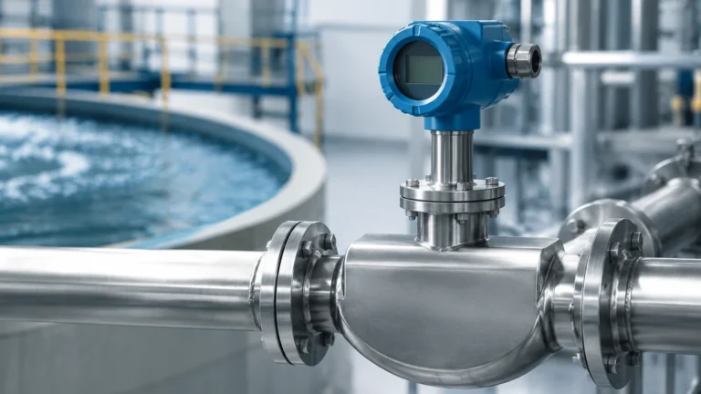
Automated sensors are designed for continuous immersion. Unlike laboratory probes, industrial sensors are ruggedized to withstand pressure, temperature fluctuations, and chemical abrasion. The transmitter converts the high-impedance millivolt signal from the sensor into a standardized industrial signal, such as 4-20mA, Modbus RS485, or HART.
2. Control Logic (PLC/PID)
In an automated environment, the transmitter sends data to a Programmable Logic Controller (PLC) or a dedicated PID controller. The controller compares the real-time pH value against a pre-set "setpoint." If the value deviates, the controller calculates the required corrective action.
3. Actuation and Dosing
The "action" phase of ph meter automation typically involves chemical dosing pumps or motorized valves. For instance, if a wastewater tank becomes too acidic, the controller triggers a pump to inject a specific volume of caustic soda (NaOH) until the neutral setpoint is reached.
4. Data Logging and Remote Monitoring
Automation allows for the continuous recording of pH data. This is vital for regulatory compliance in industries like pharmaceutical manufacturing or municipal water treatment, where historical proof of pH stability is required.
Integrating pH Automation with Level Control Systems
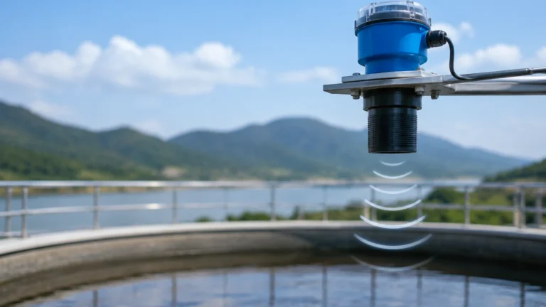
In industrial tank management, pH control rarely exists in a vacuum. It is frequently paired with level measurement technologies to ensure safe and efficient chemical processing. For example, in a neutralization tank, an automated pH system manages the chemical balance, while a radar level meter or ultrasonic sensor—technologies specialized by Welk—monitors the tank volume to prevent overfills during dosing.
When these systems are integrated, the PLC can use level data to adjust dosing logic. If a tank is only 20% full, the automation system will inject smaller increments of neutralizing agents compared to when the tank is at 80% capacity, preventing "overshoot" and ensuring a faster return to the setpoint.
Selection Criteria for Industrial pH Automation
Choosing the right equipment requires an analysis of the specific process environment. The following table provides a general guide for selecting sensors based on common industrial applications:
| Application Type | Recommended Sensor Feature | Typical Temperature Range | Pressure Considerations |
| :— | :— | :— | :— |
| Water Treatment | General purpose glass, gel-filled | 0°C to 60°C (32°F to 140°F) | Low (up to 3 bar / 43 psi) |
| Chemical Processing | PTFE junction, high-temp glass | -5°C to 110°C (23°F to 230°F) | High (up to 10 bar / 145 psi) |
| Food & Beverage | Hygienic design, solid electrolyte | 0°C to 135°C (32°F to 275°F) | Medium (SIP/CIP compatible) |
| Wastewater (Oily) | Flat surface glass, easy-clean | 0°C to 80°C (32°F to 176°F) | Low to Medium |
Key Evaluation Factors
* Junction Type: For liquids with high solids or oils, an open junction or a Teflon (PTFE) junction is preferred to prevent clogging.
* Electrolyte Choice: Gel-filled sensors are low-maintenance but non-refillable. Liquid-filled sensors allow for electrolyte replenishment, extending the life of the probe in harsh conditions.
* Cable Length and Shielding: Because pH signals are high-impedance, they are susceptible to electromagnetic interference. Automated systems should use double-shielded cables or utilize digital sensors that convert the signal at the probe head.

Installation Guidelines and Best Practices
Proper installation is the most significant factor in the reliability of ph meter automation. Even the most advanced controller cannot compensate for a poorly placed sensor.
1. Orientation: Sensors should never be installed horizontally or upside down. A minimum angle of 15° above the horizontal is required to ensure the internal electrolyte stays in contact with the glass membrane and to prevent air bubbles from being trapped in the sensor tip.
2. Flow Velocity: In-line sensors should be placed where the flow is steady but not excessively turbulent. High velocity can cause "streaming potentials" (static noise), while stagnant areas may result in a slow response time that lags behind the actual process changes.
3. Grounding: Ensure the process liquid is properly grounded. Stray currents in metal piping or tanks can interfere with the low-voltage pH signal, leading to significant measurement drift.
4. Accessibility: Automated sensors require periodic calibration. Install them in locations where they can be easily removed via a retractable assembly or a bypass line without shutting down the entire process.
Limitations and Maintenance Challenges
While ph meter automation significantly reduces manual labor, it does not eliminate the need for maintenance. Users should be aware of the following limitations:
* Sensor Aging: All pH electrodes have a finite lifespan, typically 6 to 18 months depending on the environment. The glass membrane gradually loses its sensitivity, and the reference electrolyte eventually becomes contaminated.
* Coating and Fouling: In applications like lime softening or oily wastewater treatment, the sensor tip can become coated. Automated cleaning systems (using water jets or chemical sprays) can be integrated into the ph meter automation loop to mitigate this.
* Calibration Drift: Even the best automated systems require periodic manual calibration against standard buffer solutions (usually pH 4, 7, and 10). Most industrial transmitters feature a "calibration timer" to alert operators when this is necessary.
Frequently Asked Questions (FAQs)
Q: Can I use a standard lab pH probe for industrial automation?
A: It is not recommended. Lab probes lack the mechanical strength, pressure ratings, and temperature resistance required for continuous industrial use. They will likely fail within days in a process environment.
Q: How far can the transmitter be from the pH sensor?
A: For analog sensors, the distance should generally be kept under 15 meters (50 feet) to avoid signal degradation. If longer distances are required, a pre-amplifier or a digital sensor (Modbus/HART) should be used.
Q: Does ph meter automation work in non-aqueous liquids?
A: pH measurement is defined by hydrogen ion activity in water. While it is possible to measure pH in some solvent-water mixtures, specialized electrodes and non-standard calibration procedures are required for non-aqueous or low-conductivity fluids.
Q: How often should an automated pH system be calibrated?
A: This depends entirely on the process. In stable water treatment applications, once a month may suffice. In harsh chemical reactors, weekly or even daily calibration might be necessary to maintain the required accuracy.
By implementing robust ph meter automation, industrial facilities can achieve a level of process stability that manual sampling simply cannot match. When combined with reliable level measurement and control, these systems form the backbone of modern, efficient industrial automation.