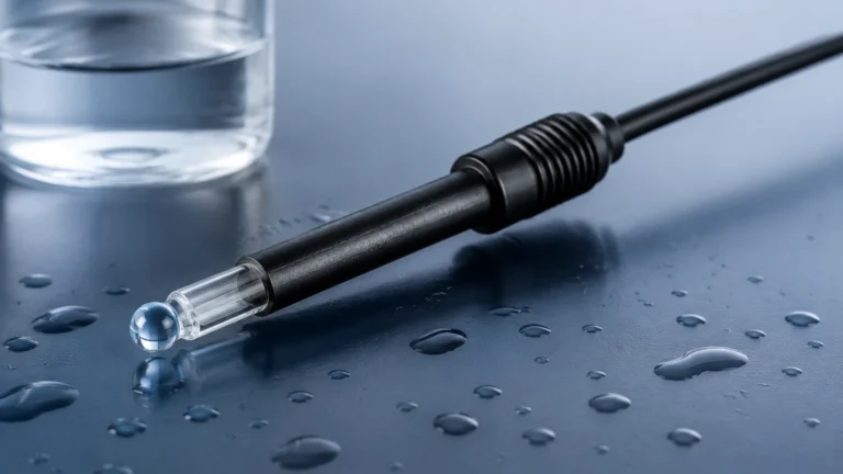
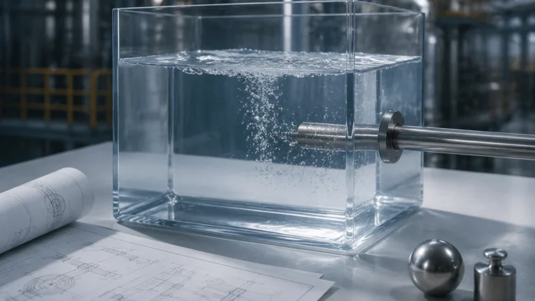
Turbidity Measuring Unit
Turbidity Measuring Unit
In industrial process control and environmental monitoring, the clarity of a liquid is often as critical as its level or flow rate. A turbidity measuring unit is a precision instrument designed to quantify the concentration of suspended solids or undissolved matter in a liquid by measuring the loss of transparency. Whether in municipal water treatment, chemical processing, or food and beverage production, understanding the technical nuances of these units is essential for maintaining product quality and regulatory compliance.
As a professional manufacturer of industrial measurement instruments, Welk provides a comprehensive range of solutions for industrial automation. While level measurement remains a core focus, the integration of liquid quality sensors, such as a turbidity measuring unit, is often required to provide a complete picture of process health. To explore our full suite of industrial instrumentation, you may visit our Main Page.
Measurement Principles of Turbidity
Before selecting a turbidity measuring unit, it is vital to understand the physics of how light interacts with particles in a fluid. Turbidity is not a direct measurement of the mass of suspended solids, but rather an optical property that describes how light is scattered or absorbed by those particles.
1. Nephelometry (90° Light Scattering)
This is the most common principle used for low to medium turbidity ranges. A light source (typically an LED or tungsten lamp) sends a beam into the liquid. Sensors are positioned at a 90-degree angle to the light path. When the light hits suspended particles, it scatters in various directions. The intensity of the light scattered at 90 degrees is proportional to the concentration of particles. This method is highly sensitive and is the standard for drinking water applications.
2. Light Attenuation (Transmission)
In this method, the sensor is placed directly opposite the light source (180 degrees). The unit measures the decrease in light intensity as it passes through the fluid. While less sensitive than nephelometry at low levels, transmission measurement is effective for high-turbidity liquids, such as sludge or concentrated chemical slurries, where scattering becomes too complex to measure accurately.
3. Backscattering
For extremely high concentrations of solids, sensors may measure light reflected back toward the source (often at 135 or 180 degrees). This is frequently used in industrial wastewater and pulp and paper applications where the liquid is nearly opaque.
Understanding Turbidity Units and Standards
The output of a turbidity measuring unit can be expressed in several different units, depending on the optical design and the regulatory standard followed (e.g., ISO 7027 or EPA 180.1).
* NTU (Nephelometric Turbidity Units): The most widely used unit, based on the EPA 180.1 standard using a white light source.
* FNU (Formazin Nephelometric Units): Used in the ISO 7027 standard, which specifies an infrared light source (860 nm) to minimize the interference of color in the liquid.
* FTU (Formazin Turbidity Units): Often used interchangeably with NTU when Formazin is used as the calibration standard.
* FAU (Formazin Attenuation Units): Used when turbidity is measured via light transmission rather than scattering.
Key Components of an Industrial Turbidity Measuring Unit
A robust industrial turbidity system typically consists of three primary components:
1. The Sensor (Probe): Contains the light source and the photodetectors. In industrial settings, these are often housed in stainless steel or chemically resistant plastics like PVC or PEEK.
2. The Controller (Transmitter): Processes the raw optical signal into a digital or analog output (e.g., 4-20mA, Modbus RS485). It also provides the user interface for calibration and configuration.
3. The Flow Cell or Mounting Hardware: Depending on the application, the sensor may be submerged directly in a tank (immersion) or installed in a bypass line (flow cell) to ensure a steady, bubble-free flow across the optics.
Practical Selection Table for Turbidity Units
Choosing the right unit requires balancing the measurement range with the physical properties of the process fluid.
| Application Type | Expected Range | Recommended Principle | Typical Sensor Housing |
| :— | :— | :— | :— |
| Drinking Water Treatment | 0 – 10 NTU | Nephelometry (90°) | PVC / Stainless Steel |
| Process Water / Cooling | 0 – 100 NTU | Nephelometry | Stainless Steel |
| Wastewater Effluent | 0 – 1000 NTU | Nephelometry / Ratio | Stainless Steel / PEEK |
| Sludge / High Solids | > 2000 NTU | Backscattering / Absorption | Reinforced Polymer |
| Chemical Processing | Variable | Infrared (ISO 7027) | PTFE / Hastelloy |

Installation Considerations
The accuracy of a turbidity measuring unit is heavily dependent on its installation environment. Engineers should consider the following factors during the design phase:
Bubble Interference
Air bubbles scatter light in the same way as solid particles, leading to false high readings. In pressurized lines, bubbles may stay in solution, but in open channels or bypass lines, they can be problematic. Using a "de-bubbler" or a specialized flow cell with a baffle system is recommended for high-precision applications.
Flow Velocity
The flow rate should be high enough to prevent particles from settling on the sensor face but low enough to avoid cavitation or excessive turbulence. A typical flow rate for a bypass turbidity measuring unit is between 200 mL/min and 700 mL/min.
Ambient Light
External light can interfere with the optical detectors. Sensors installed in open tanks should be submerged deep enough to avoid sunlight, or a light-shielding shroud should be used.
Orientation
For inline installations, the sensor should ideally be placed in a vertical pipe with the flow moving upward. This ensures the pipe is always full and helps prevent the accumulation of sediment or air pockets on the optical windows.
Maintenance and Limitations
Window Fouling
The most common challenge in turbidity measurement is the buildup of biofilm, scale, or grease on the optical windows. To mitigate this, many modern units feature:
* Automatic Wipers: Mechanical blades that periodically clean the glass.
* Ultrasonic Cleaning: High-frequency vibrations that prevent particle adhesion.
* Non-Contact Measurement: Systems where the light beam passes through the air into the liquid, avoiding direct contact with the fluid (though these are limited to specific ranges).
Color Interference
If a liquid is highly colored (e.g., tea-colored water due to tannins), it can absorb light, leading to false low readings in white-light systems. Using an infrared (IR) light source according to ISO 7027 standards helps minimize this interference, as most colored dissolved organic matter does not absorb light in the 860 nm range.
Frequently Asked Questions (FAQ)
Q: How often should a turbidity measuring unit be calibrated?
A: For critical drinking water applications, calibration checks are often performed weekly or monthly. In industrial wastewater, a quarterly calibration is usually sufficient, provided the sensor is kept clean. Always use certified Formazin or stabilized polymer standards.
Q: Can a turbidity sensor measure Total Suspended Solids (TSS)?
A: Yes, but only through correlation. Turbidity measures light scattering, while TSS measures mass. If the particle size and composition remain constant, a turbidity unit can be calibrated to display mg/L of TSS. However, if the nature of the solids changes, the correlation will drift.
Q: What is the maximum pressure for an inline turbidity sensor?
A: Most standard industrial turbidity probes are rated for up to 6 bar (approx. 87 psi). For high-pressure applications, specialized housings or bypass systems with pressure-reducing valves are required.
Q: Does temperature affect turbidity readings?
A: While the optical measurement itself is not highly sensitive to temperature, the physical properties of the fluid (such as the solubility of certain particles) can change. Furthermore, extreme temperature fluctuations can cause condensation inside the sensor housing if it is not properly sealed.
Conclusion
A turbidity measuring unit is an indispensable tool for modern industrial automation, providing real-time data that ensures process efficiency and environmental safety. By understanding the underlying optical principles—whether nephelometry for low-range precision or backscattering for high-solids environments—engineers can select the most appropriate technology for their specific needs.
Proper installation, particularly the management of air bubbles and window fouling, remains the most critical factor in long-term reliability. When integrated with other process instruments, such as the radar or ultrasonic level meters provided by Welk, these units contribute to a robust and transparent industrial control system. For further technical specifications and product support, please refer to our Main Page.