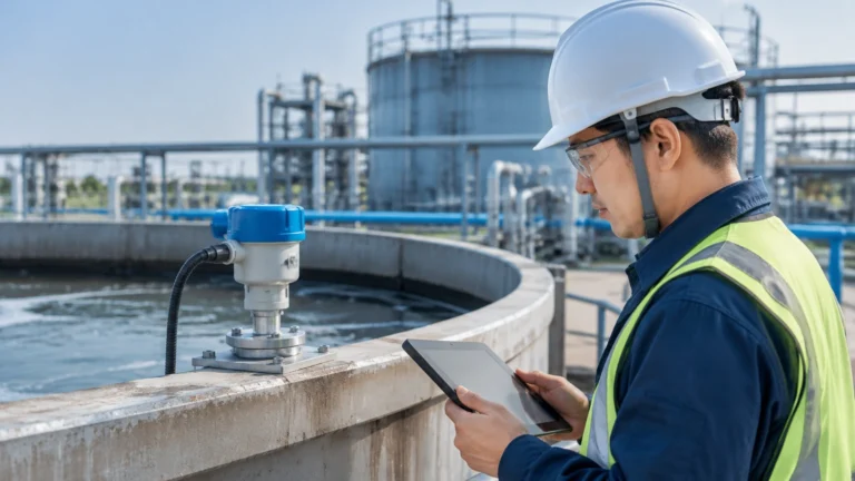
Flow Measurement Ultrasonic
Flow Measurement Ultrasonic
In the landscape of industrial process control, flow measurement ultrasonic technology has emerged as a preferred solution for operators seeking high accuracy without the maintenance burdens associated with mechanical flow meters. By utilizing sound waves to determine the velocity of a fluid, these instruments provide a non-invasive or minimally invasive method to monitor liquid and gas movement across diverse sectors, including water treatment, chemical processing, and oil and gas production.
Understanding the technical nuances of flow measurement ultrasonic is essential for engineers and procurement specialists. This guide examines the underlying physics, selection criteria, and installation requirements necessary to ensure long-term reliability in industrial environments. For those seeking comprehensive instrumentation options, visiting the Main Page of a professional manufacturer provides deeper insights into specific hardware configurations.
Principles of Ultrasonic Flow Measurement
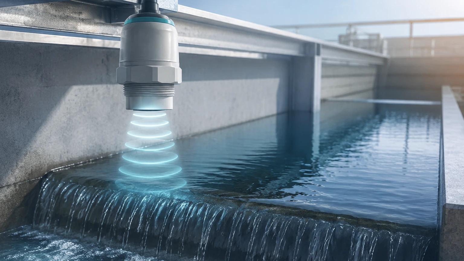
Ultrasonic flow meters operate by transmitting high-frequency sound waves (typically in the range of 0.5 to 4 MHz) through a fluid. The interaction between these sound waves and the moving fluid allows the device to calculate the flow velocity. There are two primary methods used in industrial applications: Transit-Time and Doppler Effect.
Transit-Time (Time-of-Flight)
Transit-time flow measurement is the most common method for clean liquids. It relies on the principle that a sound pulse traveling in the direction of flow will reach its destination faster than a pulse traveling against the flow.
Two transducers are mounted on the pipe, acting as both transmitters and receivers. The meter measures the time difference ($Δt$) between the upstream and downstream signals. This time difference is directly proportional to the average velocity of the fluid.
Key Equation:
$V = K · (L / 2 · cos θ) · (Δt / t_{up} · t_{down})$
Where:
* $V$ = Fluid velocity
* $L$ = Path length
* $θ$ = Angle of the ultrasonic beam
* $t$ = Travel time
This method is highly accurate (often within ±0.5% to ±1% of the flow rate) but requires the fluid to be relatively free of suspended solids or entrained air, which can scatter the signal.
Doppler Effect
Doppler flow measurement is used for fluids containing particles, bubbles, or high turbidity. It works by transmitting a continuous ultrasonic signal into the fluid. This signal reflects off moving discontinuities (solids or gas bubbles). The frequency of the reflected signal is shifted according to the velocity of the particles (the Doppler Shift).
While generally less accurate than transit-time meters (typically ±2% to ±5%), Doppler meters are indispensable for wastewater, slurries, and aerated liquids where transit-time signals would fail to penetrate.
Inline vs. Clamp-on Configurations
When selecting a system for flow measurement ultrasonic, the mechanical interface with the piping system is a critical decision point.
1. Clamp-on Ultrasonic Flow Meters
Clamp-on meters feature transducers that are strapped to the exterior of the pipe. This non-invasive approach offers several advantages:
* Zero Pressure Drop: Since there is no obstruction inside the pipe, the pumping energy is conserved.
* No Process Downtime: Installation does not require cutting the pipe or halting production.
* Chemical Compatibility: The sensors never touch the fluid, making them ideal for corrosive or ultra-pure liquids.
* Portability: These units can be moved between different measurement points for auditing purposes.
2. Inline (Wetted) Ultrasonic Flow Meters
Inline meters consist of a flow tube with integrated transducers. These are installed as a permanent part of the piping system.
* Higher Accuracy: Because the path length and angle are factory-calibrated and fixed, inline meters provide superior precision.
* Reduced Sensitivity: They are less affected by pipe wall conditions or acoustic coupling issues.
* Stability: Ideal for high-pressure or high-temperature applications where external clamp-on signals might degrade.
Key Selection Criteria for Industrial Applications
Selecting the right instrument requires a detailed analysis of the process conditions. Engineers should evaluate the following parameters before procurement:
Fluid Characteristics
* Cleanliness: If the fluid has <10,000 ppm of solids and <2% bubbles, transit-time is preferred. Above these levels, Doppler is required.
* Viscosity: High viscosity can affect the flow profile (laminar vs. turbulent). Ultrasonic meters typically require a Reynolds number ($Re$) above 10,000 for maximum accuracy, though modern signal processors can compensate for transitional flow.
* Temperature: Standard sensors handle up to 80°C (176°F), while specialized high-temperature transducers can withstand up to 250°C (482°F).
Pipe Specifications
* Material: Ultrasonic waves travel well through carbon steel, stainless steel, and most plastics (PVC, PE). However, lined pipes (e.g., cement-lined or rubber-lined) can be challenging if the liner is not perfectly bonded to the pipe wall, as air gaps will block the signal.
* Size: Ultrasonic technology is scalable from small tubes (DN15 / 0.5 inch) to massive conduits (DN6000 / 240 inches).
Performance Requirements
* Turndown Ratio: Ultrasonic meters offer excellent turndown ratios, often exceeding 100:1, allowing for accurate measurement of both peak demand and low-flow leakage.
* Output Signals: Ensure the meter supports the required integration, such as 4-20mA, Modbus RTU, or HART protocols.
Practical Selection Table
| Feature | Transit-Time (Clamp-on) | Transit-Time (Inline) | Doppler (Clamp-on) |
| :— | :— | :— | :— |
| Best Application | Clean liquids, Retrofits | High-precision custody transfer | Slurries, Wastewater |
| Accuracy | ±1.0% to ±2.0% | ±0.5% | ±2.0% to ±5.0% |
| Installation Cost | Low (No pipe cutting) | High (Flanged/Welded) | Low (No pipe cutting) |
| Maintenance | Minimal | Low | Minimal |
| Fluid Types | Water, Chemicals, Oils | All clean fluids | Aerated liquids, Pulp |
| Pipe Range | DN15 – DN6000 | DN15 – DN1000 | DN25 – DN3000 |
Installation Considerations and Best Practices
To achieve the theoretical accuracy of flow measurement ultrasonic, strict adherence to installation guidelines is mandatory. The most common cause of measurement error is poor transducer placement.
Straight Pipe Runs
Ultrasonic meters require a fully developed flow profile. As a general rule, provide a straight run of at least 10D upstream (10 times the pipe diameter) and 5D downstream from the sensor location. If the installation is near a pump or a partially open valve, the upstream requirement may increase to 30D or more to eliminate turbulence.
Mounting Methods for Clamp-on Sensors
1. V-Method: Used for pipes with diameters from DN15 to DN200. The signal bounces off the opposite wall once. It is easy to install and provides a good signal-to-noise ratio.
2. Z-Method: Used for larger pipes (above DN200) or where the fluid is slightly attenuating. The transducers are placed on opposite sides of the pipe, and the signal crosses the pipe once.
3. W-Method: Used for very small pipes (DN15 to DN50) to increase the path length and improve resolution.
Acoustic Coupling
For clamp-on meters, air is the enemy of the ultrasonic signal. A coupling agent (silicone grease or acoustic gel) must be applied between the transducer face and the pipe wall to eliminate air gaps. In permanent installations, solid epoxy or stainless steel foils may be used.
Orientation
On horizontal pipes, sensors should be mounted at the "3 o'clock" and "9 o'clock" positions. Avoid the top of the pipe (where air bubbles collect) and the bottom (where sediment settles), as both will interfere with the signal.
Limitations and Risks
While versatile, flow measurement ultrasonic technology has specific limitations:
* Acoustic Short-Circuiting: In some metal pipes, the sound may travel through the pipe wall faster than through the fluid, creating "noise" that masks the actual flow signal.
* Liner Separation: If an internal pipe liner becomes delaminated, the resulting air gap will completely block the ultrasonic beam.
* Extreme Aeration: If gas volume fraction (GVF) exceeds 5-10% in a transit-time meter, the signal will likely be lost.
* Power Requirements: While low-power versions exist, most high-performance ultrasonic meters require a stable power supply, though battery-powered units are available for remote water monitoring.
Frequently Asked Questions (FAQ)
Q: Can ultrasonic flow meters measure steam?
A: Specialized high-temperature transit-time meters can measure dry or saturated steam, but it requires specific transducers and signal processing to handle the high velocities and temperature variations.
Q: How often do clamp-on sensors need recalibration?
A: The electronics themselves are very stable. However, the coupling gel can dry out over several years. It is recommended to check signal strength annually and re-apply couplant if the signal-to-noise ratio drops.
Q: Does pipe wall thickness matter?
A: Yes. The meter must be programmed with the exact pipe wall thickness and material to calculate the refraction angle of the sound wave correctly. An ultrasonic thickness gauge is often used during setup to confirm this value.
Q: Can these meters measure flow in both directions?
A: Yes, transit-time ultrasonic meters are inherently bi-directional. They can measure and totalize flow in both forward and reverse directions, which is useful for storage and distribution networks.
Conclusion
Flow measurement ultrasonic represents a sophisticated balance of physics and digital signal processing. By selecting the appropriate method—transit-time for clean fluids or Doppler for challenging slurries—and ensuring meticulous installation, industrial operators can achieve precise flow monitoring with minimal maintenance.
Before finalizing a system design, it is vital to confirm pipe materials, fluid properties, and the required straight-run availability. For a detailed review of available hardware and technical support for your specific application, visit the Main Page to explore professional-grade measurement solutions.