Flow Meter Analog
Flow Meter Analog
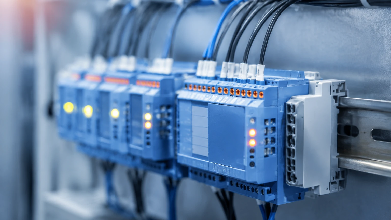
In industrial automation and process control, the ability to monitor fluid movement in real-time is fundamental to operational efficiency and safety. A flow meter analog device serves as a critical bridge between physical fluid dynamics and electronic control systems. By converting the kinetic energy or volumetric displacement of a fluid into a continuous electrical signal, these instruments allow Programmable Logic Controllers (PLCs) and Distributed Control Systems (DCS) to maintain precise control over chemical dosing, water treatment, and oil and gas distribution.
While digital communication protocols like Modbus or HART are increasingly common, the analog signal—specifically the 4-20mA current loop—remains the global standard for flow measurement due to its reliability, simplicity, and resistance to electrical noise. This guide explores the principles, selection criteria, and installation requirements for analog flow measurement systems.
Measurement Principles of Analog Flow Meters
An analog flow meter functions by translating a physical measurement (velocity, pressure, or volume) into a proportional electrical value. The two most common analog outputs are current loops and voltage signals.
The 4-20mA Current Loop
The 4-20mA signal is the most prevalent analog output in industrial environments. In this configuration, a flow rate of zero is represented by 4mA, and the maximum rated flow (full scale) is represented by 20mA. This "live zero" at 4mA is a significant safety feature; if the signal drops to 0mA, the control system immediately identifies a wire break or instrument failure rather than a zero-flow condition. Because current does not drop over long distances in a series circuit, these meters can be located hundreds of meters away from the controller without signal degradation.
Voltage Signals (0-5V or 0-10V)
Voltage-based analog outputs represent flow through a linear voltage scale. While easier to interface with some basic data loggers, voltage signals are highly susceptible to electromagnetic interference (EMI) and voltage drops over long cable runs. Consequently, they are typically reserved for localized equipment or laboratory settings where the distance between the sensor and the receiver is less than 10 meters.
Transduction Technologies
To generate these signals, the meter must first sense the flow using one of several physical principles:
* Electromagnetic: Uses Faraday’s Law of Induction, where a conductive fluid moving through a magnetic field generates a voltage proportional to its velocity.
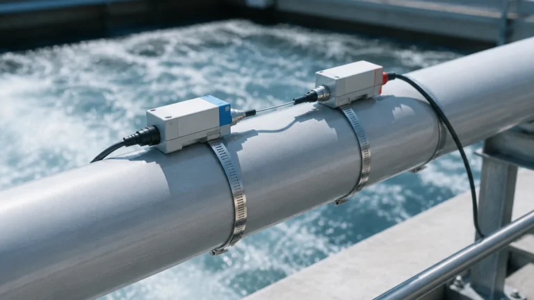
* Ultrasonic: Measures the time-of-flight difference between sound waves traveling upstream and downstream.
* Differential Pressure (DP): Measures the pressure drop across an orifice plate or Venturi tube, where the square root of the pressure drop is proportional to the flow rate.
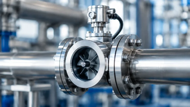
* Turbine: Uses a rotor that spins at a speed proportional to the flow velocity, which is then converted by a transmitter into an analog signal.
Key Evaluation Criteria for Flow Meter Analog Selection
Selecting the correct flow meter analog system requires a thorough analysis of the fluid properties and the environmental conditions of the installation site. Engineers must balance accuracy requirements against the total cost of ownership.
Fluid Characteristics
The chemical compatibility of the meter’s wetted parts (the materials in contact with the fluid) is the first priority. For example, corrosive acids require PTFE-lined electromagnetic meters, while ultrapure water might necessitate non-invasive ultrasonic sensors. Viscosity also plays a role; turbine meters may lose accuracy with high-viscosity liquids, whereas positive displacement meters excel in those conditions.
Flow Range and Turndown Ratio
The turndown ratio defines the range over which a meter can measure accurately. If a meter has a full scale of 100 m³/h and a turndown ratio of 10:1, it can provide reliable analog data down to 10 m³/h. Operating below this range results in significant signal noise and inaccuracy. For applications with wide fluctuations in flow, such as municipal water distribution, a high turndown ratio is essential.
Accuracy and Repeatability
In B2B industrial applications, accuracy is typically expressed as a percentage of the measured value or a percentage of the full-scale range. For billing or custody transfer, high-accuracy meters (±0.5% or better) are required. For simple process monitoring, a meter with ±2% accuracy may be sufficient and more cost-effective.
Practical Selection Table
The following table provides a comparison of common analog flow meter technologies used in industrial automation.
| Technology | Typical Signal | Best Application | Fluid Type | Accuracy (Typical) |
| :— | :— | :— | :— | :— |
| Electromagnetic | 4-20mA | Wastewater, Slurries | Conductive Liquids | ±0.5% |
| Ultrasonic | 4-20mA / 0-10V | Large Pipes, Retrofits | Clean Liquids | ±1.0% to ±2.0% |
| Turbine | 4-20mA / Pulse | Fuel, Solvents | Low Viscosity | ±0.25% to ±0.5% |
| Vortex | 4-20mA | Steam, Compressed Air | Gas, Steam, Liquid | ±1.0% |
| Variable Area | 4-20mA (via transmitter) | Local Monitoring | Gas, Liquid | ±2.0% to ±5.0% |
For detailed specifications on how these technologies integrate with broader level and flow management systems, engineers can Review product options and application support to ensure compatibility with existing infrastructure.
Installation and Wiring Considerations
The performance of a flow meter analog output is often determined more by the quality of the installation than by the instrument itself. Improper wiring or piping configurations are the leading causes of measurement error.
Piping Requirements
Most flow meters require a "fully developed flow profile" to measure accurately. This means the fluid must travel through a straight section of pipe before and after the meter to eliminate turbulence caused by elbows, valves, or pumps. A general rule is to provide 10 diameters (10D) of straight pipe upstream and 5 diameters (5D) downstream. For example, a 100mm (approx. 4-inch) pipe requires a 1000mm straight run before the meter.
Signal Shielding and Grounding
Analog signals are sensitive to EMI from high-voltage equipment like Variable Frequency Drives (VFDs) and motors.
1. Shielded Cable: Always use shielded twisted-pair (STP) cabling for 4-20mA loops.
2. Single-Point Grounding: The cable shield should be grounded at only one end (usually the PLC side) to prevent ground loops, which can introduce a DC offset into the flow reading.
3. Separation: Analog signal wires should be run in separate conduits from AC power lines, maintaining a minimum distance of 300mm where possible.
Power Supply
Analog meters are either 2-wire or 4-wire.
* 2-Wire (Loop Powered): The meter draws its operating power directly from the 4-20mA current loop. This simplifies wiring but limits the power available for features like backlit displays or heating elements.
* 4-Wire: Separate pairs of wires are used for power (e.g., 24VDC or 110VAC) and the analog signal. This is common for high-power devices like electromagnetic meters.
Limitations and Common Risks
Despite their ubiquity, analog flow measurement systems have inherent limitations that must be managed through proactive engineering.
Signal Attenuation and Noise
While 4-20mA is robust, it is not immune to all interference. In environments with heavy industrial machinery, high-frequency noise can "ride" on the DC signal, causing the flow reading to fluctuate or "jitter." Installing a signal isolator or a low-pass filter at the PLC input can help stabilize the reading.
Calibration Drift
Electronic components in the transmitter can drift over time due to temperature fluctuations or component aging. This results in the 4mA signal no longer representing exactly zero flow. Regular calibration using a calibrated current source is necessary to maintain system integrity. Many modern instruments include internal temperature compensation to mitigate this risk.
Fluid Limitations
Analog meters are often calibrated for specific fluid properties. If the fluid density or viscosity changes significantly (e.g., due to a change in process temperature), the analog output may no longer accurately reflect the volumetric or mass flow unless the transmitter is reprogrammed with new compensation factors.
Frequently Asked Questions (FAQ)
Q: Can I convert a 4-20mA signal to a 0-10V signal?
A: Yes. By placing a 500-ohm precision resistor across the input terminals of a voltage-sensing device, a 4-20mA signal will produce a 2-10V drop. However, this should only be done for local monitoring, as it lacks the noise immunity of a true current loop.
Q: Why is my flow meter showing 3.8mA instead of 4mA?
A: A reading slightly below 4mA (often referred to as "under-range") usually indicates that the pipe is empty or that the sensor is detecting a slight negative flow/vacuum. If it drops significantly lower (e.g., 0-2mA), it typically indicates a hardware fault or a broken wire.
Q: How far can I run a 4-20mA analog signal?
A: The maximum distance depends on the power supply voltage and the total resistance (impedance) of the wire and the receiving device. With a standard 24VDC supply, distances of up to 1,000 meters are common using 18 AWG (0.8 mm²) wire.
Q: Do analog flow meters require periodic maintenance?
A: Yes. Beyond electrical calibration, the physical sensor may require cleaning. For instance, electrodes in electromagnetic meters can become coated with scale or grease, which insulates them from the fluid and degrades the signal. Mechanical meters with moving parts, like turbines, require inspection for bearing wear.
Conclusion
The flow meter analog remains a vital component of the industrial landscape, offering a standardized and reliable method for process data transmission. By understanding the underlying physics of the 4-20mA loop and adhering to strict installation guidelines regarding straight pipe runs and electrical shielding, facilities can ensure long-term accuracy and minimal downtime. When selecting a system, always verify that the meter's technology aligns with the specific conductivity, viscosity, and temperature of the process media. For engineers seeking to integrate these instruments into a comprehensive level and flow control strategy, consulting a professional manufacturer for OEM/ODM customization can provide the necessary technical edge in complex automation environments.