Flow Meter Electromagnetic
Flow Meter Electromagnetic
In the landscape of industrial process control, the flow meter electromagnetic—often referred to as a magmeter—stands as a cornerstone technology for measuring the volumetric flow of conductive liquids. Unlike mechanical flow meters that rely on moving parts, electromagnetic flow meters utilize the principles of physics to provide high-accuracy measurements with minimal maintenance. This guide serves as a practical engineering reference for selecting, installing, and maintaining electromagnetic flow meters within diverse industrial environments, ranging from water treatment to chemical processing.
Measurement Principle: Faraday’s Law of Induction
The operation of a flow meter electromagnetic is based on Faraday’s Law of Electromagnetic Induction. This law states that a voltage is induced when a conductive medium moves through a magnetic field. In the context of a flow meter, the medium is the process liquid, and the magnetic field is generated by coils located within the meter body.
The mathematical representation of this principle is defined by the equation:
E = k · B · v · D
Where:
* E is the induced voltage (signal).
* k is a constant related to the specific instrument.
* B is the magnetic field strength.
* v is the average velocity of the conductive liquid.
* D is the inner diameter of the measuring pipe (the distance between electrodes).
As the liquid flows through the pipe, it acts as a moving conductor. The magnetic field coils, powered by the transmitter, create a constant magnetic field perpendicular to the flow direction. Two electrodes placed on opposite sides of the pipe wall detect the induced voltage. Since the magnetic field (B) and the pipe diameter (D) are constant, the induced voltage is directly proportional to the flow velocity (v). The transmitter then converts this microvolt signal into a standard output, such as 4-20mA, pulse, or digital communication protocols like Modbus or HART.
Key Components and Construction
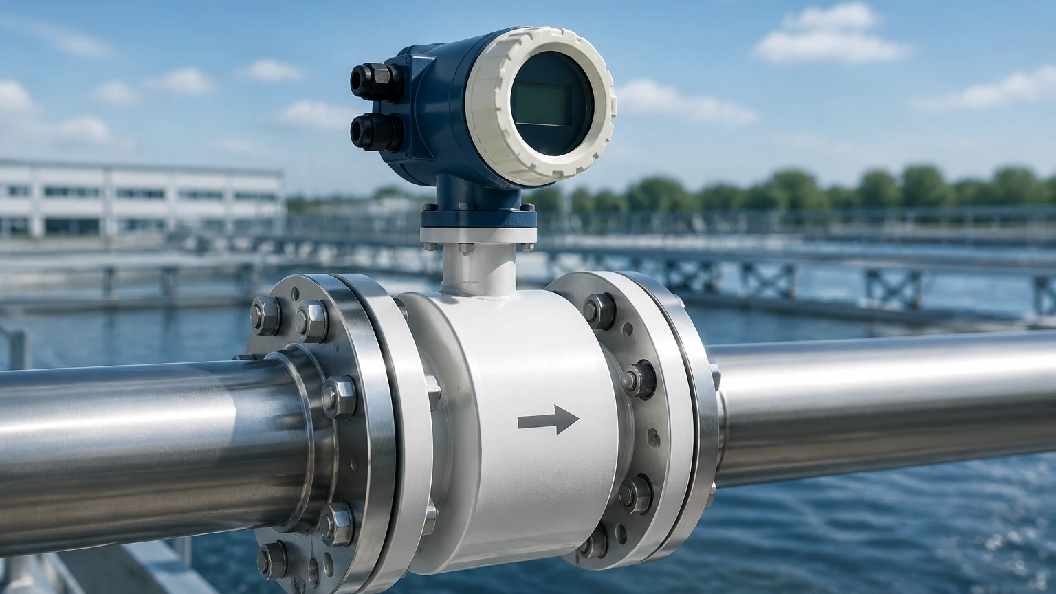
To ensure durability and accuracy in harsh industrial environments, a flow meter electromagnetic is constructed with several critical components:
1. Measuring Tube: Typically made of non-magnetic stainless steel to prevent interference with the magnetic field.
2. Liner: An insulating material that lines the interior of the measuring tube. It prevents the induced voltage from short-circuiting through the metal pipe and protects the meter from corrosion and abrasion.
3. Electrodes: A pair of conductive pins that make contact with the fluid to pick up the induced voltage. They must be resistant to the chemical properties of the process medium.
4. Magnetic Coils: Located outside the measuring tube but inside the meter housing, these generate the necessary magnetic field.
5. Transmitter (Converter): The electronics that process the electrode signal, perform calculations, and provide the user interface and output signals.
Technical Selection Criteria
Choosing the correct flow meter electromagnetic requires a thorough understanding of the process conditions. Because the meter relies on electrical induction, the most fundamental requirement is that the fluid must be electrically conductive. Most magmeters require a minimum conductivity of 5 μS/cm (microsiemens per centimeter).
Material Compatibility
The choice of liner and electrode material is the most critical factor in ensuring the longevity of the instrument. The following table provides a general selection guide for common industrial applications:
| Application | Recommended Liner | Recommended Electrode | Notes |
| :— | :— | :— | :— |
| Potable Water | Hard Rubber / EPDM | SS316L | Focus on hygienic certifications. |
| Wastewater / Sewage | Polyurethane / Hard Rubber | SS316L / Hastelloy C | Resistance to solids and mild chemicals. |
| Strong Acids (HCl, H2SO4) | PTFE / PFA | Tantalum / Platinum | High chemical resistance required. |
| Abrasive Slurries | Ceramic / Thick Rubber | Tungsten Carbide | Focus on mechanical wear resistance. |
| High-Temperature Fluids | PFA / Ceramic | Stainless Steel | PFA handles up to 180°C. |
Sizing and Flow Velocity
Unlike valves, which are often sized to the pipe diameter, a flow meter electromagnetic should be sized based on flow velocity. The optimal velocity range for most magmeters is between 2 m/s and 6 m/s (approx. 6.5 to 20 ft/s).
* If the velocity is too low (< 0.5 m/s): The induced voltage signal becomes very weak, leading to decreased accuracy and potential signal noise issues.
* If the velocity is too high (> 10 m/s): Excessive friction may damage the liner, and pressure drops across the meter may become significant.
For comprehensive technical support and to explore a wide range of industrial instrumentation, engineers can visit the Main Page for detailed specifications and product options.
Installation Considerations
Proper installation is paramount to achieving the specified accuracy (typically ±0.5% or better). Even the most advanced flow meter electromagnetic will provide unreliable data if installed incorrectly.
Straight Pipe Runs
To ensure a stable and symmetrical flow profile, magmeters require a certain length of straight pipe before and after the sensor. The standard rule of thumb is "5D and 2D":
* Upstream: 5 times the nominal pipe diameter of straight pipe.
* Downstream: 2 times the nominal pipe diameter of straight pipe.
If there are significant disturbances upstream, such as a partially open valve or a pump, the upstream requirement may increase to 10D or more.
Pipe Orientation and Filling
The measuring tube must always be completely full of liquid. Air bubbles or partially filled pipes will cause significant measurement errors.
* Vertical Installation: This is the preferred orientation, with the flow moving upward. This ensures the pipe remains full and prevents air pockets from forming at the electrodes.
* Horizontal Installation: The meter should be installed in a low point of the piping system (a U-trap configuration) to ensure it stays flooded. The electrodes must be positioned horizontally (at the 3 o'clock and 9 o'clock positions) to prevent them from being covered by sediment at the bottom or air at the top.
Grounding
Since the induced voltage signal is in the millivolt or microvolt range, any stray electrical currents in the piping can interfere with the measurement. Proper grounding is essential. This involves bonding the meter body to the process fluid. In metal piping, this is usually achieved through grounding straps. In plastic or lined piping, grounding rings must be installed between the flanges to provide a path to the fluid.
Limitations and Prohibitions
While the flow meter electromagnetic is versatile, it is not a universal solution. Engineers must be aware of the following limitations:
* Non-Conductive Fluids: Magmeters cannot measure hydrocarbons (oils, diesel, gasoline), deionized water, or gases. These fluids lack the necessary ions to induce a voltage.
* Gas Entrainment: Large amounts of entrained air or gas bubbles will cause the meter to over-read or fluctuate wildly.
* Vacuum Conditions: Certain liners, particularly PTFE, can collapse or pull away from the pipe wall under vacuum conditions. If a vacuum is possible, a PFA liner with a reinforced mesh should be specified.
* Magnetic Interference: High-power cables or large motors located in close proximity to the meter can distort the magnetic field and affect accuracy.
Integration with Level Measurement Systems
In many industrial applications, flow measurement is used in conjunction with level measurement to provide a complete picture of process efficiency. For instance, in a chemical storage facility, a radar level meter monitors the total volume in a tank, while a flow meter electromagnetic measures the precise amount of chemical being pumped out for processing.
Welk provides a comprehensive suite of industrial instruments, including radar level meters and ultrasonic sensors, that work in tandem with flow measurement technologies to automate industrial processes. By integrating these data points into a centralized PLC or SCADA system, facilities can optimize inventory management and detect leaks or process inefficiencies in real-time.
Maintenance and Troubleshooting
One of the primary advantages of the flow meter electromagnetic is the lack of moving parts, which significantly reduces the need for routine maintenance. However, certain conditions may require attention:
* Electrode Coating: In applications involving fats, oils, or sticky substances, a film can build up on the electrodes, insulating them from the fluid. Some modern magmeters include an electrode cleaning circuit or replaceable electrodes to mitigate this.
* Liner Wear: In abrasive slurry applications, the liner should be inspected periodically for thinning. High-performance ceramic liners are often used to extend the service life in these environments.
* Zero-Point Check: Periodically, the meter should be checked for a "zero" reading when the flow is completely stopped but the pipe remains full. If the meter shows a flow rate when there is none, a zero-point calibration may be necessary.
Frequently Asked Questions (FAQ)
Q: Can a flow meter electromagnetic measure flow in both directions?
A: Yes, most modern magmeters are bi-directional. They can be configured to measure flow in both directions and provide separate totalizers for forward and reverse flow.
Q: What is the maximum temperature a magmeter can handle?
A: This depends on the liner material. Hard rubber is typically limited to 80°C, while PFA and Ceramic liners can handle temperatures up to 150°C or 180°C, respectively.
Q: How does fluid density or viscosity affect the measurement?
A: One of the greatest strengths of the electromagnetic principle is that it is independent of fluid density, viscosity, pressure, and temperature, provided the conductivity remains above the minimum threshold.
Q: Is a flow meter electromagnetic suitable for hygienic applications?
A: Yes. Models with stainless steel housings, PFA liners, and Tri-Clamp fittings are specifically designed for the food, beverage, and pharmaceutical industries, meeting 3-A or EHEDG standards.
Conclusion
The flow meter electromagnetic remains a preferred choice for industrial liquid measurement due to its accuracy, reliability, and low pressure drop. By understanding the underlying physical principles and adhering to strict installation and selection guidelines, engineers can ensure long-term performance even in the most challenging environments. For those seeking to optimize their process loops with high-quality instrumentation, reviewing the available technology and support on the Main Page is a recommended next step in the engineering process.