Welded Display Magmeter
Welded Display Magmeter
In the landscape of industrial process control, the welded display magmeter represents a specialized evolution of the electromagnetic flowmeter. Designed for environments where durability, hermetic sealing, and high-precision measurement are non-negotiable, these instruments are critical components in water treatment, chemical processing, and food production. This guide provides an engineering-focused overview of the technology, its selection criteria, and the practical considerations necessary for successful deployment in industrial systems.
Operating Principle of Electromagnetic Flowmeters
The fundamental operation of a welded display magmeter is based on Faraday’s Law of Electromagnetic Induction. This principle states that a voltage is induced when a conductive fluid moves through a magnetic field. In a practical industrial application, the magmeter consists of a non-ferromagnetic tube lined with an insulating material. Two electromagnetic coils are placed around the tube to generate a constant magnetic field ($B$).
As a conductive liquid flows through the tube at a velocity ($v$), it acts as a moving conductor. This motion induces an electromotive force (voltage, $E$) that is perpendicular to both the direction of the flow and the magnetic field. This relationship is expressed by the formula:
$$E = B \cdot v \cdot D$$
Where:
- $E$ is the induced voltage.
- $B$ is the magnetic field strength.
- $v$ is the average velocity of the fluid.
- $D$ is the inner diameter of the pipe (the distance between the electrodes).
Because the magnetic field strength and the pipe diameter are constant, the induced voltage is directly proportional to the flow velocity. Two electrodes, typically made of corrosion-resistant alloys, detect this voltage and transmit it to the transmitter’s electronics. The transmitter then converts this signal into a standardized output, such as a 4-20mA signal or a digital pulse, which is displayed on the integrated welded display unit.
Key Features of Welded Display Magmeters
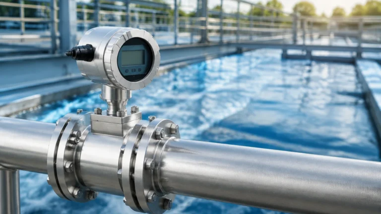
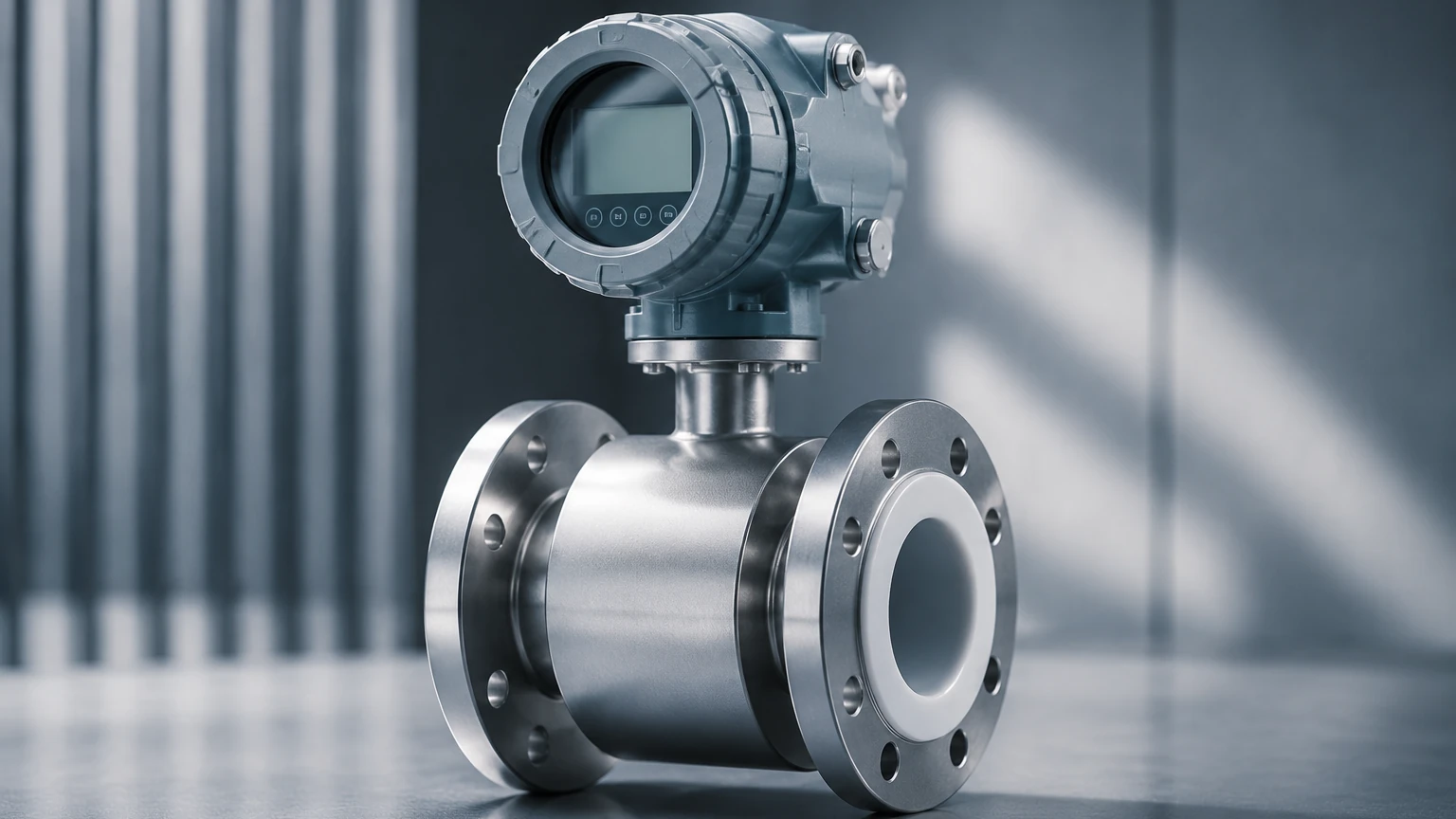
The term "welded display" specifically refers to the construction of the transmitter housing and the interface. Unlike standard meters that may use bolted covers or plastic enclosures, a welded display magmeter features a hermetically sealed stainless steel housing where the display window is integrated through advanced welding or high-strength bonding techniques. This design offers several distinct advantages:
1. Superior Ingress Protection
Industrial environments often involve high-pressure wash-downs, steam, or exposure to corrosive atmospheres. The welded construction ensures an IP68 rating, meaning the internal electronics are completely protected against dust and continuous submersion in water. This prevents the fogging of the display and the internal corrosion of circuit boards.
2. Enhanced Vibration Resistance
In heavy industrial settings, mechanical vibration can loosen fasteners on traditional bolted housings. The unified structure of a welded housing provides greater structural integrity, ensuring that the display remains functional and the internal components remain secure over years of operation.
3. Hygienic and Chemical Integrity
For the pharmaceutical and food industries, crevices in bolted housings can harbor bacteria. A smooth, welded exterior minimizes these risks. In chemical plants, the absence of gaskets in the housing prevents aggressive vapors from penetrating the transmitter enclosure.
Selection Criteria and Technical Specifications
Selecting the correct welded display magmeter requires a thorough understanding of the process fluid and the installation environment. Engineers must evaluate several technical parameters to ensure long-term accuracy and reliability. For more comprehensive instrument options and technical support, professionals often consult the Main Page of specialized manufacturers like Welk.
Fluid Conductivity
The most critical requirement for any magmeter is that the fluid must be conductive. Generally, a minimum conductivity of 5 μS/cm (microsiemens per centimeter) is required. This makes magmeters unsuitable for hydrocarbons, distilled water, or non-polar solvents.
Liner and Electrode Materials
The internal liner protects the meter body from the process fluid and provides electrical insulation. Common materials include:
- PTFE (Teflon): Excellent for high temperatures and aggressive chemicals.
- Hard Rubber: Suitable for water treatment and abrasive slurries.
- PFA: Used for high-purity applications and vacuum resistance.
Electrodes must be compatible with the chemical properties of the fluid. Options typically include Stainless Steel 316L, Hastelloy C, Tantalum, or Titanium.
Practical Selection Table
The following table provides a general guideline for selecting meter sizes and materials based on common industrial applications.
| Application Type | Recommended Liner | Electrode Material | Typical Size Range (mm) | Flow Velocity Range |
| :— | :— | :— | :— | :— |
| Potable Water | EPDM / Hard Rubber | SS316L | 25mm – 2000mm | 0.5 – 10 m/s |
| Corrosive Chemicals | PTFE / PFA | Hastelloy C / Tantalum | 10mm – 600mm | 0.3 – 8 m/s |
| Abrasive Slurries | Polyurethane | Tungsten Carbide | 50mm – 400mm | 1.0 – 5 m/s |
| Food & Beverage | PFA (FDA Grade) | SS316L / Titanium | 10mm – 150mm | 0.5 – 10 m/s |
| Wastewater | Hard Rubber | SS316L | 50mm – 1200mm | 0.5 – 12 m/s |
Installation Guidelines for Optimal Accuracy
Even the highest quality welded display magmeter will underperform if installed incorrectly. To maintain the specified accuracy (typically ±0.5% or better), the following installation rules must be observed:
Straight Pipe Requirements
To ensure a stable and symmetrical flow profile, the meter requires a straight run of pipe both upstream and downstream. The standard engineering rule is "5D and 2D":
- Upstream: At least 5 times the nominal pipe diameter of straight pipe.
- Downstream: At least 2 times the nominal pipe diameter of straight pipe.
If there are control valves or pumps immediately upstream, these distances may need to be increased to 10D or more.
Pipe Orientation and Filling
The meter must always be full of liquid. If the pipe is only partially full, the meter will provide inaccurate, erratic readings.
- Vertical Installation: The flow should move upwards. This ensures the pipe remains full and prevents air bubbles from collecting at the electrodes.
- Horizontal Installation: The meter should be installed at a low point in the piping system. The electrodes should be oriented horizontally (at the 3 o'clock and 9 o'clock positions) to avoid interference from air at the top or sediment at the bottom.
Grounding and Electrical Noise
Since the induced voltage is very small (often in the millivolt range), electrical noise can easily distort the signal. The meter must be properly grounded to the process fluid. In plastic or lined piping systems, grounding rings must be installed on both sides of the meter to provide a path for the electrical reference.
Limitations and Application Constraints
While the welded display magmeter is a robust tool, it is not a universal solution. Engineers must be aware of the following limitations:
1. Conductivity Dependency: As mentioned, it cannot measure non-conductive fluids like oils or deionized water.
2. Temperature Limits: The maximum operating temperature is constrained by the liner material. While PTFE can handle up to 180°C (356°F), other liners like polyurethane are limited to 60°C (140°F).
3. Pressure Constraints: The welded housing provides external protection, but the internal pressure rating is determined by the flange standard (e.g., PN16, PN40, or ANSI 150/300).
4. Entrained Air: Large bubbles or significant aeration in the fluid will cause the meter to over-read or lose the signal entirely.
Frequently Asked Questions (FAQs)
Q: Can a welded display magmeter measure steam or gas?
A: No. Electromagnetic flowmeters only work with conductive liquids. Steam and gases do not have the necessary conductivity to induce a voltage.
Q: How often does the meter need calibration?
A: In stable applications like clean water, calibration may only be needed every 2–3 years. However, in abrasive or corrosive applications where the liner might wear or electrodes might scale, annual verification is recommended.
Q: What is the benefit of the "welded" aspect specifically?
A: The welded design is primarily about environmental protection. It prevents moisture from entering the transmitter housing, which is the leading cause of electronic failure in humid or outdoor industrial environments.
Q: Does the meter require a specific flow direction?
A: Most modern magmeters are bi-directional. However, they are usually calibrated in one primary direction. It is important to check the arrow on the meter body during installation.
Conclusion
The welded display magmeter is an essential instrument for modern industrial automation, offering a blend of electromagnetic precision and structural durability. By understanding the underlying physics of Faraday's Law and adhering to strict installation and material selection standards, engineers can ensure reliable flow measurement in the most demanding conditions. For those seeking specific product configurations or OEM/ODM services, visiting the Main Page of an established manufacturer like Welk provides access to the technical expertise required to match the instrument to the application's unique demands.