Flowline Piping
Flowline Piping
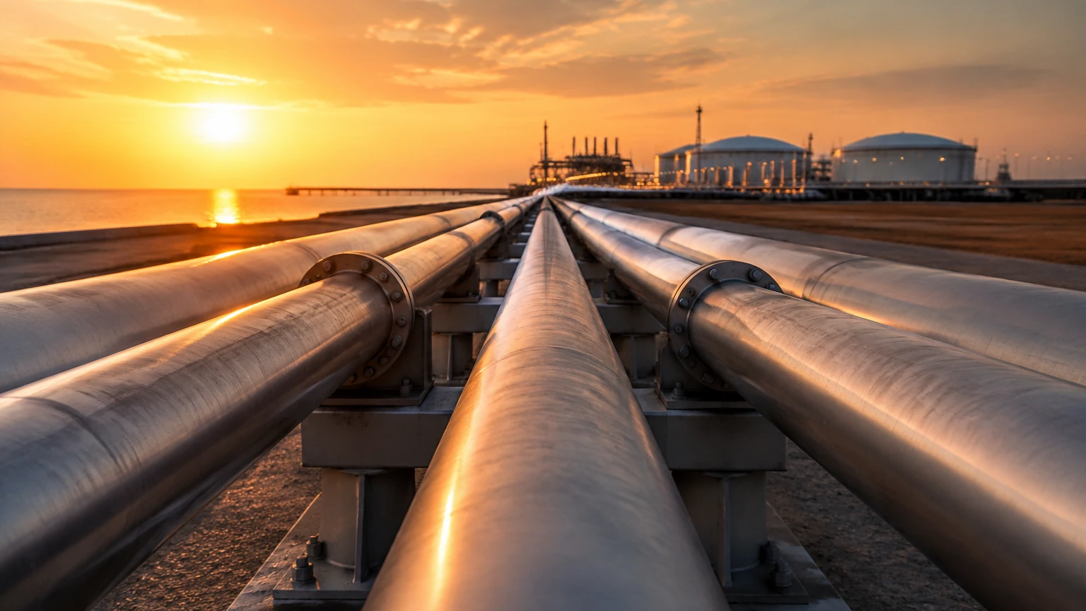
In industrial fluid management, particularly within the oil and gas, chemical, and water treatment sectors, the architecture of fluid transport is fundamental to operational efficiency. Flowline piping refers to the specialized conduits that transport raw fluids—often a mixture of oil, gas, water, or chemical precursors—from a source, such as a wellhead or a primary storage tank, to a processing facility or a manifold. Unlike distribution lines that carry refined products to end-users, flowline piping must handle untreated, often multiphase fluids under varying pressures and temperatures.
Effective management of these systems requires precise monitoring of the vessels and separators to which these pipes connect. Level measurement instrumentation is critical in this context, ensuring that separators do not overflow and that pumps are protected from dry running. As a professional manufacturer, Welk provides a range of industrial level measurement instruments designed to integrate seamlessly with the demanding environments of flowline piping networks.
The Role of Level Measurement in Flowline Piping Systems
Flowline piping does not exist in isolation; it is part of a complex loop that includes separators, surge tanks, and slug catchers. The primary objective of level instrumentation in these systems is to provide real-time data for process control and safety.
In a typical upstream application, flowline piping delivers a mixture of fluids into a horizontal or vertical separator. Here, the liquid levels of oil and water must be accurately determined to facilitate phase separation. If the level is too high, liquid can carry over into gas lines (liquid carryover), potentially damaging compressors. Conversely, if the level is too low, gas can enter the liquid lines (gas blow-by), causing cavitation in downstream pumps and inaccuracies in flow metering.
For engineers and operators, selecting the right level sensor for the vessels connected to flowline piping involves understanding the physical properties of the fluid, the dynamics of the flow, and the environmental conditions of the site. To explore our comprehensive range of solutions, you can visit the Main Page of our product catalog.
Principles of Level Measurement Technologies
Before selecting an instrument for a flowline-related application, it is essential to understand the underlying physical principles of the various technologies available.
1. Radar Level Measurement (ToF)
Radar level meters operate on the Time-of-Flight (ToF) principle. The device emits high-frequency electromagnetic waves (typically in the 26GHz or 80GHz range) toward the product surface. These waves are reflected back to the sensor. The distance is calculated based on the time interval between transmission and reception.
* Non-Contact Radar: Ideal for corrosive or viscous fluids found in flowline piping systems, as the sensor does not touch the medium.
* Guided Wave Radar (GWR): Uses a probe to guide the signal. This is particularly effective for fluids with low dielectric constants or when there is significant turbulence or foam in the vessel.
2. Ultrasonic Level Sensors
Ultrasonic sensors emit mechanical sound pulses. The time it takes for the pulse to reflect off the liquid surface and return to the transducer determines the level. While cost-effective, these are best suited for atmospheric tanks or water treatment applications where the vapor space is relatively stable and free of heavy dust or steam.
3. Hydrostatic Level Transmitters
This technology measures the pressure exerted by a liquid column. Based on the formula $P = \rho gh$ (where $P$ is pressure, $\rho$ is density, $g$ is gravity, and $h$ is height), the transmitter calculates the level. Hydrostatic sensors are highly reliable for vented tanks but require a constant fluid density for accurate readings.
4. Magnetic Level Gauges
Magnetic gauges utilize a bypass chamber connected to the side of a vessel or a section of flowline piping. A float containing a permanent magnet moves with the liquid level, actuating a visual indicator or a transmitter outside the chamber. This provides a clear, high-pressure-rated visual reference without the risks associated with glass sight gauges.
Technical Selection Criteria for Flowline Instrumentation
When designing a system that incorporates flowline piping, the selection of level instruments must be guided by several technical parameters:
1. Fluid Composition: Is the fluid a single phase or multiphase? For oil-water interfaces common in flowline separators, Guided Wave Radar or specialized magnetic floats are often preferred.
2. Process Pressure and Temperature: Flowline piping in the oil and gas sector often operates at high pressures (up to 10 MPa or more) and temperatures. Instruments must be rated for these extremes. Welk offers customized OEM/ODM services to ensure sensors meet specific pressure vessel codes.
3. Dielectric Constant (εr): Radar performance depends on the reflectivity of the medium. Water has a high dielectric constant (~80), making it easy to detect, while some hydrocarbons have low constants (~2.0), requiring more sensitive radar or guided wave technology.
4. Turbulence and Foam: Flowlines often discharge into tanks with significant velocity, creating turbulence. In such cases, stilling wells or Guided Wave Radar are necessary to ensure a stable signal.
Installation Guidelines for Piping and Vessels
Correct installation is as important as the technology itself. Poorly placed sensors in a flowline piping network can lead to "ghost" echoes or erratic readings.
* Nozzle Placement: Sensors should not be installed directly above the inlet of the flowline piping. The incoming fluid stream will interfere with the signal. A minimum distance of 500 mm (approx. 20 inches) from the inlet is recommended.
* Dead Zones: Every sensor has a "dead zone" or "blocking distance" near the transducer where measurement is not possible. Ensure the nozzle height allows the sensor to be positioned above the maximum expected liquid level.
* Internal Obstructions: Avoid placing radar or ultrasonic sensors near internal tank structures like ladders, heating coils, or agitators. If obstructions are unavoidable, use a sensor with "false echo suppression" software.
* Bypass Chambers: For high-pressure flowline applications, installing the level meter in a bypass chamber (side-mounted to the vessel) isolates the sensor from turbulence and allows for maintenance without shutting down the main process line.
Maintenance and Risk Mitigation
Flowline piping systems are prone to several issues that can affect instrumentation performance over time:
* Paraffin and Scaling: In oil applications, wax (paraffin) can build up on probes or floats. Regular inspection or the use of non-contact radar can mitigate this risk.
* Corrosion: Because flowlines often carry "sour" gas (containing $H_2S$) or brine, materials of construction for sensors must be carefully chosen. Stainless steel 316L, Hastelloy, or PTFE coatings are common requirements.
* Signal Interference: In gas-saturated environments, the speed of sound (for ultrasonic) or the strength of the radar signal can be attenuated. Regular calibration against a manual dip-tape or a magnetic gauge is a best practice for safety-critical systems.
Comparison of Level Measurement Technologies
| Technology | Accuracy | Pressure Range | Temp Range | Best Use Case |
| :— | :— | :— | :— | :— |
| Radar (80GHz) | ±2 mm | Up to 160 bar | -40 to 250°C | Chemical tanks, high-precision storage |
| Guided Wave Radar | ±5 mm | Up to 400 bar | -50 to 450°C | Interface measurement, turbulent liquids |
| Ultrasonic | ±0.25% FS | Atmospheric | -40 to 80°C | Water treatment, open channels |
| Hydrostatic | ±0.1% FS | Varies by seal | -20 to 100°C | Deep wells, vented water tanks |
| Magnetic Gauge | ±10 mm | Up to 320 bar | -196 to 450°C | High-pressure visual monitoring |
Frequently Asked Questions (FAQ)
Q: How does flow velocity in flowline piping affect level measurement?
A: High velocity at the discharge point creates turbulence and surface ripples. This can cause signal scattering for non-contact radar and ultrasonic sensors. Using a stilling well or a bypass pipe helps provide a calm surface for accurate measurement.
Q: Can I use one sensor for both oil and water levels?
A: Yes, Guided Wave Radar (GWR) is specifically designed for this. It can detect the top of the oil layer and the interface where water begins, provided the upper liquid (oil) has a lower dielectric constant than the lower liquid (water).
Q: What is the maximum length for flowline-related level probes?
A: For Guided Wave Radar, cable probes can extend up to 30 meters (approx. 98 feet), while rigid rods are typically limited to 6 meters (approx. 20 feet) to prevent bending and damage during transport.
Q: Are Welk instruments compatible with automated control systems?
A: Absolutely. Our instruments support standard industrial protocols including 4-20mA HART, RS485 Modbus, and Foundation Fieldbus, allowing for seamless integration with PLC and SCADA systems managing your flowline piping network.
Conclusion
Managing the complexities of flowline piping requires a robust approach to instrumentation. By understanding the principles of radar, ultrasonic, and hydrostatic measurement, and by adhering to strict installation and selection criteria, engineers can ensure the safety and efficiency of their industrial processes. Whether you are dealing with high-pressure separators in the oil field or chemical storage in a manufacturing plant, selecting the appropriate level meter is a critical step in system design. For further technical assistance and to view our full product range, please refer to our Main Page.