Flowmeter Ultrasonic
Flowmeter Ultrasonic
In the landscape of industrial process control, the ability to measure fluid movement without interrupting the flow or compromising the integrity of the piping system is a significant advantage. The flowmeter ultrasonic has emerged as a primary solution for these requirements, offering a non-invasive, highly accurate, and low-maintenance method for monitoring liquids across diverse industries. While often discussed alongside level measurement technologies, ultrasonic flow measurement relies on distinct acoustic principles to determine volumetric flow rates.
For engineers and facility managers, understanding the underlying physics, hardware configurations, and installation nuances of a flowmeter ultrasonic is essential for ensuring long-term operational efficiency. This guide provides a technical overview of ultrasonic flow technology, its practical applications, and the criteria necessary for selecting the right instrument for specific industrial environments.
Fundamental Principles of Ultrasonic Flow Measurement
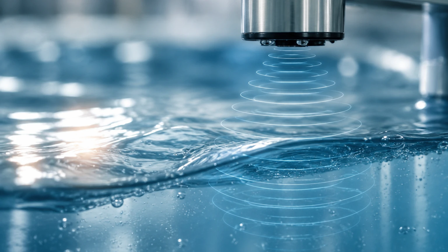
Ultrasonic flowmeters operate by transmitting high-frequency sound waves (typically in the range of 0.5 to 4 MHz) through a moving fluid. The interaction between these sound waves and the fluid allows the device to calculate the flow velocity. There are two primary methods used in industrial applications: Transit-Time and Doppler Effect.
Transit-Time Method
The transit-time flowmeter ultrasonic is the most common variant, primarily used for clean liquids. It utilizes a pair of transducers that function as both transmitters and receivers. These transducers are mounted on opposite sides of a pipe, or in a staggered configuration.
The device measures the time it takes for an ultrasonic pulse to travel from the upstream transducer to the downstream transducer ($t_{up}$) and compares it to the time taken for a pulse to travel from the downstream transducer to the upstream transducer ($t_{down}$). When the fluid is moving, the pulse traveling with the flow moves faster than the pulse traveling against it. The difference in time ($Δt$) is directly proportional to the velocity of the fluid.
Transit-time meters are highly accurate (often within ±0.5% to ±1% of the flow rate) but require relatively clean fluids to prevent signal scattering. If the liquid contains excessive bubbles or suspended solids, the ultrasonic signal may be blocked, leading to measurement failure.
Doppler Effect Method
The Doppler flowmeter ultrasonic is designed for "dirty" liquids, such as wastewater, slurries, or aerated fluids. This method relies on the frequency shift of a sound wave reflected off moving particles or gas bubbles within the liquid.
A transducer emits a continuous ultrasonic signal into the pipe. When this signal hits a moving particle (the "reflector"), it bounces back to a receiver at a different frequency. This frequency shift is proportional to the velocity of the particle, which is assumed to be moving at the same speed as the bulk fluid. For a Doppler meter to function, the fluid must contain a minimum concentration of particles or bubbles (typically at least 100 parts per million of particles larger than 75 to 100 microns).
Key Categories: Clamp-on vs. Inline Flowmeters
When selecting a flowmeter ultrasonic, the mechanical interface with the piping system is a critical decision point.
Clamp-on Ultrasonic Flowmeters
Clamp-on systems are non-invasive. The transducers are strapped to the outside of the pipe using mounting rails or chains. This configuration offers several advantages:
* No Process Downtime: Installation does not require cutting the pipe or shutting down the process.
* Zero Pressure Drop: Since there is no obstruction inside the pipe, there is no energy loss associated with the measurement.
* Chemical Compatibility: The sensors never touch the process fluid, making them ideal for corrosive or high-purity liquids.
* Portability: Portable clamp-on units are frequently used for system audits and troubleshooting.
Inline Ultrasonic Flowmeters
Inline flowmeters consist of a factory-calibrated pipe section (spool piece) with integrated transducers. These are typically used in custody transfer or high-precision industrial applications. Because the distance between transducers and the pipe geometry are fixed and calibrated at the factory, inline meters generally offer higher accuracy and better performance at very low flow velocities compared to clamp-on versions.
Technical Evaluation and Selection Criteria
Choosing the correct flowmeter ultrasonic requires an analysis of the fluid properties, pipe characteristics, and environmental conditions. The following table summarizes the primary selection factors for the two main ultrasonic technologies.
| Feature | Transit-Time Ultrasonic | Doppler Ultrasonic |
| :— | :— | :— |
| Primary Fluid Type | Clean liquids (water, oils, chemicals) | Dirty liquids (slurries, sewage, aerated fluids) |
| Suspended Solids/Bubbles | < 1% to 2% by volume | > 0.01% (100 ppm) required |
| Typical Accuracy | ±0.5% to ±2% of rate | ±2% to ±5% of full scale |
| Pipe Size Range | 15 mm to 6,000 mm | 25 mm to 6,000 mm |
| Flow Velocity Range | 0.01 m/s to 12 m/s | 0.05 m/s to 10 m/s |
| Installation Type | Inline or Clamp-on | Mostly Clamp-on |
Pipe Material and Condition
For clamp-on meters, the pipe material must be a good conductor of sound. Carbon steel, stainless steel, cast iron, and most plastics (PVC, HDPE) are suitable. However, pipes with internal liners (such as cement or rubber) or significant internal scaling can present challenges. If the liner is not perfectly bonded to the pipe wall, an air gap may exist, which will completely block the ultrasonic signal.
Installation Guidelines for Optimal Accuracy
The accuracy of a flowmeter ultrasonic is heavily dependent on the installation environment. Engineers must adhere to specific spatial requirements to ensure a fully developed flow profile.
Straight Pipe Run Requirements
To minimize turbulence and swirl, which can distort velocity measurements, the meter should be installed in a straight section of pipe. The standard industry recommendation is the "10D Upstream / 5D Downstream" rule. This means there should be at least 10 times the pipe's internal diameter of straight pipe before the meter and 5 times the diameter after the meter. If there are valves or pumps upstream, these requirements may increase to 20D or 30D.
Transducer Mounting Orientations
For horizontal pipes, transducers should be mounted at the "3 o'clock" and "9 o'clock" positions (the sides of the pipe). Mounting at the top (12 o'clock) should be avoided as air bubbles often collect there, while mounting at the bottom (6 o'clock) can be problematic due to sediment buildup. Both conditions interfere with signal transmission.
Mounting Methods (V, W, and Z)
* V-Method: The signal bounces once off the opposite pipe wall. This is the standard for pipes from 25 mm to 400 mm.
* W-Method: The signal bounces three times. This is used for very small pipes (typically under 50 mm) to increase the signal path length and improve resolution.
* Z-Method: The transducers are mounted on opposite sides of the pipe, and the signal travels directly across. This is used for large-diameter pipes (over 500 mm) or pipes with high attenuation where a reflected signal would be too weak.
Limitations and Operational Risks
While highly versatile, the flowmeter ultrasonic is not a universal solution. Certain factors can degrade performance or lead to complete signal loss:
1. Acoustic Short-Circuiting: In some metal pipes, the ultrasonic signal may travel through the pipe wall faster than through the fluid, creating noise that makes it difficult for the electronics to distinguish the actual flow signal.
2. Reynolds Number Sensitivity: Transit-time meters are sensitive to the flow regime (laminar vs. turbulent). Modern digital signal processing (DSP) helps compensate for this, but accuracy may decrease in the transition zone (Reynolds numbers between 2,000 and 4,000).
3. Temperature Extremes: While transducers can be designed for high temperatures, standard clamp-on sensors often have limits (e.g., up to 150°C or 200°C). Thermal expansion of the pipe can also affect the transducer alignment and the coupling agent's effectiveness.
4. Coupling Agent Degradation: Clamp-on sensors require a coupling gel or epoxy to eliminate air gaps between the sensor and the pipe. Over time, this gel can dry out or wash away, requiring periodic maintenance to re-apply the couplant.
Frequently Asked Questions (FAQs)
Q: Can an ultrasonic flowmeter measure gas flow?
A: Yes, but gas flowmeters require much higher frequency transducers and more powerful signal processing because gases are significantly less dense than liquids and attenuate sound waves more rapidly. They are typically inline spool-piece designs rather than clamp-on.
Q: How does pipe wall thickness affect the measurement?
A: For clamp-on meters, the wall thickness is a critical parameter for calculating the exact path of the sound wave. An incorrect thickness entry in the flow computer will result in an incorrect flow calculation. Engineers should use an ultrasonic thickness gauge to verify the pipe wall before setup.
Q: Can I use a transit-time meter on raw sewage?
A: Generally, no. Raw sewage contains high levels of suspended solids and entrained gases that scatter transit-time signals. A Doppler-style meter or an electromagnetic flowmeter is usually preferred for such applications.
Integrating Flow and Level Measurement Solutions
In many industrial processes, flow measurement is intrinsically linked to level measurement. For instance, in open-channel flow (such as flumes and weirs), the flow rate is calculated based on the liquid level measured by an ultrasonic level sensor. Similarly, in tank inventory management, monitoring both the level and the inflow/outflow via a flowmeter ultrasonic provides a redundant check on material balance and helps detect leaks.
Welk provides a comprehensive range of instrumentation designed to meet these integrated needs. As a professional manufacturer, Welk offers not only advanced radar and ultrasonic level sensors but also the technical expertise required to implement reliable measurement systems in water treatment, chemical processing, and industrial automation. For those seeking to optimize their process monitoring, you can Review product options and application support at the Welk Main Page to find cost-effective and accurate solutions tailored to specific global standards.
By carefully considering fluid properties, pipe geometry, and installation requirements, engineers can leverage ultrasonic technology to achieve precise flow monitoring with minimal maintenance, ensuring the long-term reliability of their industrial systems.