Flowmeting
Flowmeting
In the landscape of industrial process control, flowmeting—the systematic measurement of fluid movement through a system—stands as a cornerstone of operational efficiency, safety, and fiscal accountability. Whether managing the intake of raw water in a treatment facility or monitoring the precise delivery of chemical reagents in a processing plant, accurate flowmeting ensures that systems operate within their designed parameters. For engineers and facility managers, understanding the intersection between flow dynamics and measurement technology is essential for selecting the right instrumentation.
While flowmeting often involves dedicated inline flowmeters, it is frequently achieved through the application of level measurement technologies, particularly in open-channel environments or through hydrostatic calculations. This guide explores the principles of flowmeting, the technologies used to achieve it, and the critical selection criteria for industrial applications.
The Significance of Flowmeting in Industrial Automation
Flowmeting is not merely about measuring velocity; it is about quantifying volume or mass over time. In B2B sectors such as oil and gas, chemical production, and water management, flow data serves several critical functions:
1. Process Control: Maintaining the correct ratio of ingredients in a continuous chemical reaction.
2. Custody Transfer: Providing accurate data for the sale or transfer of fluids between parties.
3. Efficiency Monitoring: Identifying leaks or blockages within a piping network by comparing upstream and downstream flow rates.
4. Regulatory Compliance: Ensuring that wastewater discharge remains within legal limits.
To achieve these goals, engineers must look beyond the sensor itself and consider the entire hydraulic profile of the installation.
Fundamental Measurement Principles
Flowmeting technologies are generally categorized by the physical principle they employ to derive flow data. Below are the primary methods used in modern industrial environments.
1. Velocity-Based Measurement
Velocity-based flowmeting assumes that if the cross-sectional area of a pipe or channel is known, the flow rate (Q) can be calculated by multiplying that area (A) by the average velocity (v) of the fluid (Q = A × v).
* Ultrasonic Flowmeting: This method uses sound waves to determine velocity. Transit-time ultrasonic meters send pulses across a pipe; the time difference between pulses traveling with the flow and against it is proportional to the fluid's velocity. Doppler ultrasonic meters, conversely, reflect sound waves off particles or bubbles in the fluid to measure frequency shifts.
* Electromagnetic Flowmeting: Based on Faraday’s Law of Electromagnetic Induction, these meters measure the voltage generated when a conductive liquid moves through a magnetic field. This is highly effective for water and slurries but cannot be used with non-conductive fluids like oils.
2. Differential Pressure (DP) Flowmeting
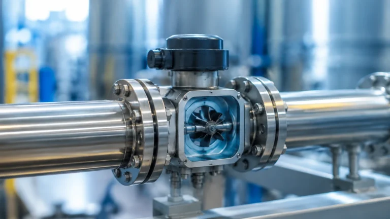
This is one of the oldest and most reliable forms of flowmeting. By placing a restriction in the pipe (such as an orifice plate or Venturi tube), a pressure drop is created. According to Bernoulli’s principle, the square root of this pressure drop is proportional to the flow rate. Hydrostatic level transmitters are often used in conjunction with these primary elements to measure the pressure difference.
3. Open Channel Flowmeting (Level-to-Flow)
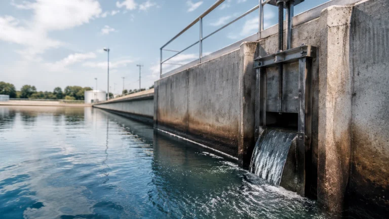
In many water treatment and irrigation applications, fluids do not flow in closed pipes but in open channels, flumes, or over weirs. In these scenarios, flowmeting is achieved by measuring the liquid level (head) at a specific point. Because the geometry of the flume or weir is fixed, a specific level always corresponds to a specific flow rate. This is where high-precision radar and ultrasonic level meters become the primary tools for flowmeting.
Flowmeting via Level Measurement
For many projects, the most cost-effective and reliable way to perform flowmeting is through non-contact level measurement. Welk specializes in these types of industrial level measurement instruments, which are essential for open-channel flow calculations. You can explore these technical solutions on the Main Page of our product catalog.
Ultrasonic Level Sensors in Flowmeting
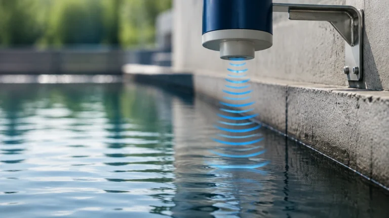
Ultrasonic sensors emit high-frequency sound pulses that reflect off the liquid surface. By calculating the time-of-flight, the sensor determines the exact level of the fluid. In a Parshall flume, for example, the transmitter uses a programmed conversion table (or a mathematical formula like the Manning equation) to translate that level into a real-time flow rate (m³/h or GPM).
Radar Level Meters
For more challenging environments—such as those with steam, foam, or significant temperature fluctuations—radar level meters are preferred. Radar uses electromagnetic waves, which are unaffected by air density or surface turbulence. This ensures that the flowmeting data remains accurate even in volatile chemical tanks or outdoor wastewater channels subject to wind and rain.
Practical Selection Table
Choosing the right technology requires balancing accuracy requirements against the physical properties of the medium.
| Technology | Typical Application | Accuracy | Advantages | Limitations |
| :— | :— | :— | :— | :— |
| Ultrasonic (Level) | Open channels, weirs | ±0.25% of range | Non-contact, low maintenance | Affected by heavy foam or vacuum |
| Radar (80GHz) | Chemical tanks, turbulent flow | ±2 mm | Extremely precise, ignores steam | Higher initial cost than ultrasonic |
| Hydrostatic | Vented tanks, deep wells | ±0.1% to 0.5% | Simple installation, reliable | Measures mass/pressure, not direct volume |
| Electromagnetic | Conductive liquids, sludge | ±0.5% of rate | No moving parts, no pressure drop | Requires conductive fluid ( >5μS/cm) |
| Transit-Time | Clean water, chemicals | ±1% to 2% | Can be clamp-on (non-invasive) | Requires clean fluids without solids |

Installation Guidelines and Engineering Considerations
Even the most advanced flowmeting instrument will fail to provide accurate data if installed incorrectly. Engineers must adhere to strict hydraulic requirements to ensure a stable flow profile.
1. Straight Pipe Requirements
For inline flowmeting, turbulence is the primary enemy. Most meters require a certain length of straight pipe upstream (usually 10 times the pipe diameter, or 10D) and downstream (5D) to allow the flow profile to stabilize. If elbows, valves, or pumps are located too close to the sensor, the resulting swirls and eddies will cause erratic readings.
2. Sensor Positioning
In horizontal pipe runs, sensors should typically be mounted on the side (3 o'clock or 9 o'clock positions) rather than the top or bottom. Mounting at the top can lead to errors caused by air pockets, while mounting at the bottom can result in sediment buildup interfering with the sensor face.
3. Open Channel Alignment
When using a level sensor for open-channel flowmeting, the sensor must be mounted perfectly perpendicular to the liquid surface. For weirs and flumes, the sensor must be placed at a specific distance upstream of the crest to avoid the "drawdown" effect, where the liquid level begins to drop as it accelerates over the edge.
4. Environmental Protection
In outdoor flowmeting stations, sunshields should be used to prevent solar radiation from heating the sensor housing, which can affect internal temperature compensation circuits in ultrasonic devices. Furthermore, ensuring the IP rating (e.g., IP68) matches the risk of submersion is vital for longevity.
Limitations and Common Challenges
While modern flowmeting is highly accurate, certain conditions present persistent challenges:
* Aeration and Cavitation: Bubbles in a liquid can scatter ultrasonic signals and cause electromagnetic meters to over-read volume. Cavitation, caused by rapid pressure drops, can damage both the pipe and the flowmeting equipment.
* Scaling and Coating: In chemical and wastewater applications, the buildup of lime, struvite, or biological film on the sensor face or pipe walls can change the effective diameter or dampen the signal. Non-contact radar is often the best solution here as it is less affected by buildup on the vessel walls.
* Viscosity Changes: Many flowmeting technologies are calibrated for a specific viscosity. If the temperature of a heavy oil changes significantly, its flow characteristics change, potentially requiring real-time temperature compensation to maintain accuracy.
Frequently Asked Questions (FAQs)
Q: Can I use a level meter to measure flow in a closed pipe?
A: Only if the pipe is partially full and acting as an open channel. For full pipes, an inline flowmeter (like electromagnetic or ultrasonic transit-time) or a differential pressure system is required. However, hydrostatic transmitters can be used to measure the pressure drop across a restriction in a full pipe to infer flow.
Q: How often should flowmeting equipment be calibrated?
A: This depends on the industry. In regulated water treatment, annual calibration is standard. In high-precision chemical dosing, semi-annual checks may be necessary. Many modern digital transmitters offer self-diagnostic features that can extend the time between physical calibrations.
Q: What is the advantage of 80GHz radar for flowmeting?
A: Higher frequency radar (80GHz) allows for a narrower beam angle. This is critical in flowmeting because it prevents the signal from hitting the sides of narrow flumes or pipes, ensuring that the measurement is taken only from the fluid surface.
Q: How do I handle flowmeting for non-conductive liquids?
A: Since electromagnetic meters will not work, the best options are ultrasonic transit-time meters, gear meters, or mass flowmeters (Coriolis). For tank-based flowmeting, high-accuracy radar level measurement remains a top choice.
For technical specifications and to find the right instrumentation for your flowmeting and level measurement needs, please visit our Main Page for a comprehensive overview of our industrial solutions.