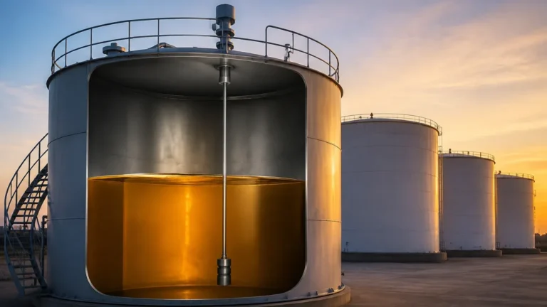
Fluid Level Sensor
Fluid Level Sensor
In the landscape of modern industrial automation, the fluid level sensor serves as a fundamental component for process control, inventory management, and safety assurance. Whether managing water treatment facilities, chemical processing plants, or oil and gas storage, the ability to accurately monitor liquid volumes is essential for operational efficiency. Selecting the appropriate fluid level sensor requires a deep understanding of the underlying measurement principles, the physical properties of the media, and the environmental conditions of the installation site.
As a professional manufacturer, Welk provides a comprehensive suite of level measurement instruments designed to meet diverse industrial requirements. This guide explores the technical specifications, selection criteria, and practical application of various fluid level sensing technologies to assist engineers in making informed procurement decisions.
Core Measurement Principles of Fluid Level Sensors
Before selecting a device, it is critical to understand how different sensors interact with the fluid and the vessel environment. Measurement technologies are generally categorized into non-contact and contact methods.
1. Radar Level Measurement (Non-Contact)
Radar fluid level sensors utilize Time-of-Flight (ToF) technology. The sensor emits high-frequency microwave pulses (typically in the 26 GHz or 80 GHz range) toward the liquid surface. These pulses are reflected back to the sensor. The distance ($D$) is calculated based on the time delay ($t$) and the speed of light ($c$):
$$D = \frac{c \times t}{2}$$
Radar technology is highly valued for its immunity to temperature fluctuations, pressure changes, and the presence of dust or vacuum. The 80 GHz radar sensors, in particular, offer a narrow beam angle, allowing for precise measurement in narrow tanks or vessels with internal obstructions like agitators.
2. Ultrasonic Level Measurement (Non-Contact)
Similar to radar, ultrasonic sensors use the ToF principle but utilize sound waves instead of electromagnetic pulses. The sensor transmits an ultrasonic pulse that reflects off the fluid surface. The speed of sound is temperature-dependent, typically following the formula $v \approx 331.5 + 0.6T$ (where $T$ is temperature in Celsius). Most modern ultrasonic fluid level sensors include integrated temperature compensation to maintain accuracy. These are cost-effective solutions for water and wastewater applications but are sensitive to heavy foam, steam, and vacuum conditions.
3. Hydrostatic Level Measurement (Contact)
Hydrostatic sensors measure the pressure exerted by a liquid column at a specific depth. The relationship between pressure ($P$), density ($\rho$), gravity ($g$), and height ($h$) is defined by the formula:
$$P = \rho \times g \times h$$
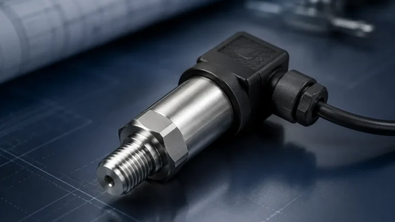
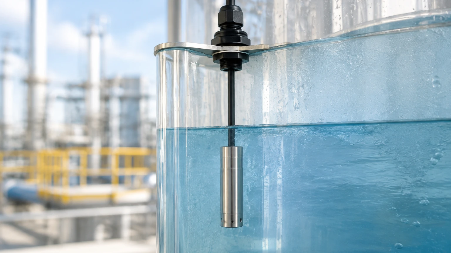
By measuring the pressure at the bottom of a tank and knowing the fluid density, the sensor calculates the level. These sensors are available as submersible probes or externally mounted flange transmitters. They are highly reliable for vented tanks but require compensation for vapor space pressure in sealed vessels.
4. Magnetic Level Gauges and Transmitters (Contact)
These devices utilize a float containing a permanent magnet that moves with the liquid level inside a bypass chamber or directly in the tank. The float’s position is detected either visually by magnetic flaps or electronically by a magnetostrictive transmitter or reed switch array. This technology provides a robust, power-free visual indication while offering high-accuracy electronic output for control systems.
Key Evaluation Criteria for Selecting a Fluid Level Sensor
Selecting the right fluid level sensor involves more than just matching a range to a tank height. Engineers must evaluate the following technical factors:
Media Characteristics
* Dielectric Constant ($\epsilon_r$): For radar sensors, the reflectivity of the fluid depends on its dielectric constant. Fluids with low $\epsilon_r$ (like hydrocarbons) reflect less energy than water-based fluids, requiring more sensitive radar units.
* Density: Hydrostatic sensors are directly affected by changes in fluid density. If the process involves fluids with varying densities, a hydrostatic sensor may require recalibration or a different technology should be considered.
* Corrosiveness: Highly acidic or alkaline fluids require sensors made from compatible materials such as PTFE, PVDF, or high-grade stainless steel (316L).
Process Conditions
* Temperature and Pressure: Ultrasonic sensors are generally limited to atmospheric or low-pressure applications and temperatures below 80°C (176°F). Radar and magnetic gauges can handle extreme temperatures exceeding 400°C (752°F) and high-pressure environments.
* Turbulence and Foam: Surface agitation can scatter ultrasonic and radar signals. In these cases, a stilling well or a guided wave radar (GWR) may be necessary to ensure a stable signal.
Accuracy and Range
Industrial applications typically require accuracy levels ranging from ±1 mm to ±10 mm. Radar sensors provide the highest precision over long distances (up to 30 meters or 100 feet and beyond), while hydrostatic sensors are excellent for deep wells and large reservoirs.
Practical Selection Table for Fluid Level Sensors
The following table provides a general comparison of common fluid level sensor technologies to assist in the initial screening process.
| Technology | Measurement Type | Typical Accuracy | Max Range (m) | Media Suitability | Relative Cost |
| :— | :— | :— | :— | :— | :— |
| 80GHz Radar | Non-contact | ±1 mm | 120m | Corrosive, High Temp, Solids | High |
| Ultrasonic | Non-contact | ±0.25% FS | 15m – 30m | Water, Wastewater, Acids | Low/Medium |
| Hydrostatic | Contact | ±0.1% – 0.5% | 200m+ | Clean liquids, Oils | Medium |
| Magnetic Gauge | Contact | ±5 mm | 6m+ | High Temp/Pressure, Oil | Medium/High |
| Level Switch | Point Level | N/A | N/A | Overfill protection | Low |
For a detailed analysis of specific models and their technical data sheets, users should consult the Main Page for a comprehensive overview of available industrial instrumentation.
Installation Considerations and Best Practices
Correct installation is as vital as sensor selection. Even the most advanced fluid level sensor will fail to provide accurate data if installed improperly.
1. Dead Zones (Blocking Distance): Every non-contact sensor has a "dead zone" directly beneath the transducer face where measurement is impossible. Ensure the sensor is mounted high enough so that the maximum fluid level never enters this zone.
2. Nozzle Geometry: For radar and ultrasonic sensors, the mounting nozzle should be as short and wide as possible. If the nozzle is too narrow or too long, it can create internal reflections (ringing) that interfere with the actual level signal.
3. Positioning: Avoid mounting sensors in the center of a tank (to prevent multiple reflections from the tank walls) or too close to the wall (to avoid beam interference). A common rule of thumb is to place the sensor at 1/6th of the tank diameter from the wall.
4. Obstructions: Ensure the signal path is clear of ladders, heating coils, or agitator blades. If obstructions are unavoidable, many modern sensors offer "false echo suppression" software to map out and ignore these static reflections.
5. Environmental Shielding: For outdoor installations, use a sunshade to prevent temperature-induced errors in ultrasonic sensors and to protect the electronics from UV degradation.
Limitations and Common Risks in Fluid Level Measurement
While modern fluid level sensor technology is highly advanced, certain limitations must be acknowledged to avoid system failure.
* Vapor and Condensation: In ultrasonic sensors, heavy steam can change the speed of sound, leading to significant errors. Condensation on the sensor face can also "blind" the transducer. Radar is generally immune to vapor but can be affected by heavy condensation if the droplets become large enough to attenuate the signal.
* Build-up and Scaling: Contact sensors like hydrostatic probes or magnetic floats are susceptible to build-up. In wastewater or viscous chemical applications, material can coat the sensor, leading to sluggish response or total failure. Non-contact radar is the preferred solution for coating-prone media.
* Ambient Noise: High-frequency acoustic noise from pneumatic filling or machinery can interfere with ultrasonic sensors. In such environments, electromagnetic radar is a more robust choice.
* Power Supply Stability: Many industrial sensors operate on a 4-20mA loop. Fluctuations in power supply or electromagnetic interference (EMI) from nearby motors can introduce noise into the signal. Using shielded cables and proper grounding is mandatory.
Frequently Asked Questions (FAQs)
Q: How often should a fluid level sensor be calibrated?
A: Calibration frequency depends on the technology and the criticality of the application. Hydrostatic sensors may require annual checks due to potential sensor drift. Radar and ultrasonic sensors are generally more stable but should be verified during scheduled plant shutdowns or if process conditions change significantly.
Q: Can one sensor be used for multiple types of fluids?
A: It depends on the technology. Radar is very versatile across different fluids as long as the dielectric constant is sufficient. Hydrostatic sensors, however, must be recalibrated if the fluid density changes, as they measure weight rather than volume.
Q: What is the difference between a level sensor and a level switch?
A: A fluid level sensor provides continuous measurement (e.g., 0-100% or 4-20mA output), allowing for real-time monitoring of the level. A level switch provides point-level detection (on/off), typically used for high-level alarms or low-level pump protection.
Q: Is wireless transmission available for these sensors?
A: Yes, many modern sensors can be integrated with WirelessHART or LoRaWAN gateways, which is particularly useful for remote tank farms where cabling costs are prohibitive.
Conclusion
The successful implementation of a fluid level sensor system hinges on matching the physical properties of the process with the technical strengths of the measurement technology. By considering factors such as media dielectric, temperature, pressure, and tank geometry, engineers can ensure long-term reliability and accuracy. Welk continues to innovate in the field of industrial level measurement, providing customized OEM/ODM services and a wide range of radar, ultrasonic, and hydrostatic solutions. For additional technical support or to review specific product options, please visit the Main Page to connect with our engineering team.