Fluid Sensors Level
Fluid Sensors Level
In the landscape of industrial automation and process control, the accurate monitoring of fluid sensors level is a fundamental requirement. Whether managing water treatment facilities, chemical processing plants, or oil and gas storage, the ability to precisely quantify the volume or height of a liquid within a vessel ensures operational safety, inventory accuracy, and process efficiency. Selecting the appropriate technology requires a deep understanding of the physical principles governing different sensor types and the specific environmental constraints of the application.
Industrial level measurement is generally categorized into two types: point level detection and continuous level measurement. Point level sensors indicate whether a liquid has reached a specific height, often used for overfill protection or pump control. Continuous level sensors provide real-time data across the entire height of a tank, allowing for sophisticated process management. This guide explores the core technologies used in modern fluid sensors level monitoring, offering engineering insights into their selection and implementation.
Core Principles of Level Measurement Technologies
Before selecting a sensor, it is essential to understand the underlying physics that allow these instruments to detect fluid interfaces. Most industrial sensors rely on one of four primary principles: time-of-flight, pressure, buoyancy, or electrical properties.
Time-of-Flight (ToF)
Both radar and ultrasonic sensors utilize the Time-of-Flight principle. The sensor emits a signal (either an electromagnetic wave or a sound wave) that travels to the liquid surface, reflects off the interface, and returns to the receiver. By measuring the time taken for this round trip and knowing the speed of the wave in the medium (usually air or vapor), the device calculates the distance to the fluid.
* Radar (Non-contact): Uses high-frequency microwave pulses. It is largely unaffected by temperature fluctuations, vacuum, or high pressure, making it a versatile choice for complex chemical environments.
* Ultrasonic: Uses sound waves. While cost-effective, it is sensitive to air temperature changes and surface turbulence, as sound speed varies with the density of the transmission medium.
Hydrostatic Pressure
Hydrostatic level transmitters operate based on the principle that the pressure at the bottom of a liquid column is directly proportional to the height of the liquid above it, multiplied by the liquid's density and gravity ($P = \rho gh$). By measuring this pressure via a diaphragm, the sensor determines the fluid level. This method is highly reliable for vented tanks where the liquid density remains constant.
Buoyancy and Magnetism
Magnetic level gauges and float switches use a buoyant element (float) that moves with the liquid surface. In a magnetic gauge, the float contains a permanent magnet that actuates external flags or a transmitter strip. This provides a clear visual indication and a secondary electronic signal without the need for the electronics to come into direct contact with the process media.
Comparative Analysis of Fluid Sensors
Choosing the right instrument involves balancing performance requirements against environmental challenges. For a comprehensive overview of available technologies, engineers often consult a Main Page of technical specifications to compare accuracy and material compatibility.
Radar Level Meters
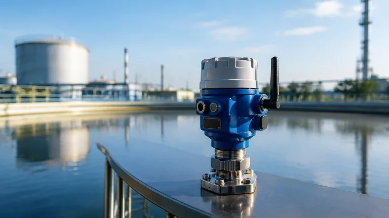
Radar technology has become the industry standard for challenging applications. Frequency-modulated continuous wave (FMCW) radar, particularly at 80GHz, offers a narrow beam angle, which minimizes interference from tank internals like ladders or agitators.
* Advantages: High precision (often within ±2 mm), non-contact measurement, and suitability for extreme temperatures (up to 450°C) and pressures.
* Limitations: High-dielectric fluids are easier to measure; fluids with very low dielectric constants (like certain oils) may require guided wave radar (GWR) to ensure a strong return signal.
Ultrasonic Level Sensors
Ultrasonic sensors are preferred for water and wastewater applications where the liquid is relatively calm and the atmosphere is stable.
* Advantages: Low cost, no moving parts, and easy installation.
* Limitations: Not suitable for vacuum applications (sound cannot travel in a vacuum) or high-dust environments. Foam on the liquid surface can also absorb the sound waves, leading to signal loss.
Hydrostatic Transmitters
These are often used in deep wells, reservoirs, and large storage tanks.
* Advantages: Simple to install (submersible versions exist) and very durable.
* Limitations: Accuracy is dependent on constant fluid density. If the temperature changes significantly or if different fluids are mixed, the resulting density change will cause a measurement error.
Practical Selection Table for Fluid Sensors Level
The following table provides a general guideline for selecting a measurement technology based on common industrial criteria.
| Application Criteria | Radar (Non-contact) | Ultrasonic | Hydrostatic | Magnetic Gauge |
| :— | :— | :— | :— | :— |
| Accuracy | Excellent (±1-3 mm) | Good (±0.25% range) | Moderate (±0.1-0.5%) | Good (±5-10 mm) |
| Pressure Range | Up to 160 bar | Atmospheric | Up to 40 bar | Up to 320 bar |
| Temp. Range | -40 to +450°C | -40 to +80°C | -20 to +100°C | -196 to +450°C |
| Corrosive Media | Excellent (PTFE/Ceramic) | Good (Plastic probes) | Good (Alloy/Ceramic) | Excellent (SS316/Titanium) |
| Foam Presence | Moderate Interference | High Interference | No Effect | No Effect |
| Cost | High | Low to Moderate | Moderate | Moderate to High |
Installation Considerations and Best Practices
Correct installation is as critical as sensor selection. Even the most advanced fluid sensors level instrument will fail if placed incorrectly within the process vessel.
1. Avoid the Dead Zone: Every sensor has a "blocking distance" or "dead zone" near the probe or transducer where measurement is impossible. Ensure the maximum expected fluid level does not enter this zone.
2. Nozzle Geometry: For radar and ultrasonic sensors, the mounting nozzle should be short and wide enough to prevent the signal beam from hitting the nozzle walls, which creates false echoes.
3. Agitation and Turbulence: In tanks with heavy agitation, use a stilling well or a bypass chamber to provide a calm surface for the sensor to measure. Alternatively, hydrostatic sensors are less affected by surface turbulence.
4. Avoid Obstructions: Ensure the path of the signal (for ToF sensors) is clear of internal structures like heating coils, spray balls, or structural reinforcements.
5. Alignment: For non-contact sensors, the transducer face must be perfectly parallel to the liquid surface to ensure the maximum signal return.

Limitations and Risk Mitigation
While modern sensors are robust, certain process conditions present inherent risks to measurement reliability:
* Vapor and Condensation: In high-temperature water applications, steam can attenuate ultrasonic signals. Radar is generally immune to vapor, but heavy condensation on the antenna can cause signal scattering. Using a PTFE-coated antenna or a specialized lens antenna can mitigate this.
* Build-up and Scaling: In the chemical industry, some fluids leave deposits on the sensor. Non-contact sensors are naturally more resistant to this, but even they can be affected if the antenna becomes heavily coated. Periodic cleaning or the use of air purging systems may be required.
* Density Variations: As noted, hydrostatic sensors rely on density. If a tank stores different chemicals at different times, the sensor must be recalibrated, or a different technology (like radar) should be used.
Maintenance and Troubleshooting
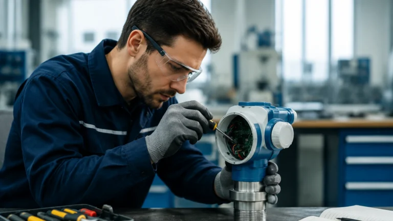
To ensure long-term reliability of fluid sensors level systems, a proactive maintenance schedule should be established. For electronic sensors, this includes checking the integrity of cable seals to prevent moisture ingress and verifying the grounding to protect against electromagnetic interference.
If a sensor provides erratic readings, the first step is to check for physical obstructions or changes in the media (such as unexpected foaming). For radar systems, reviewing the "echo curve" via diagnostic software can help identify whether the sensor is locking onto a false reflection from a tank internal rather than the actual fluid surface.
Frequently Asked Questions (FAQ)
Q: Can I use an ultrasonic sensor for measuring fuel levels?
A: It is generally not recommended. Fuel vapors can change the speed of sound, leading to significant errors. Furthermore, fuel tanks are often classified as hazardous areas, requiring explosion-proof (Ex-rated) sensors. Radar is typically the safer and more accurate choice for fuel.
Q: How does a magnetic level gauge handle high-pressure steam?
A: Magnetic gauges are excellent for high-pressure applications because the pressure is contained within a rugged metal chamber. The measurement is transmitted through the chamber wall via magnetic coupling, meaning there are no seals or glass to fail under pressure.
Q: What is the benefit of 80GHz radar over 26GHz radar?
A: 80GHz radar has a much shorter wavelength and a narrower beam. This allows it to ignore internal tank obstructions more effectively and provides better resolution, especially in small tanks or when measuring liquids with low reflectivity.
Q: Is calibration required for hydrostatic sensors?
A: Yes. Hydrostatic sensors must be calibrated to the specific gravity of the fluid being measured. If the fluid is changed from water (SG 1.0) to an oil (SG 0.8), the sensor will report a lower level than actually exists unless it is recalibrated.
By carefully evaluating the physical properties of the fluid and the mechanical constraints of the storage vessel, engineers can select fluid sensors level solutions that provide years of maintenance-free service. For detailed product options and application-specific support, visiting a professional manufacturer's Main Page is the recommended next step in the procurement process.