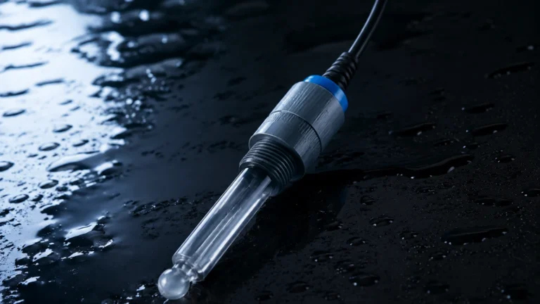
Fuel Level Monitoring Sensor
Fuel Level Monitoring Sensor
In industrial automation and logistics, the ability to accurately track fuel inventory is a cornerstone of operational efficiency. A fuel level monitoring sensor is not merely a gauge; it is a critical data point for cost control, theft prevention, and environmental compliance. Whether managing stationary backup generators, large-scale storage depots, or mobile fleet assets, selecting the appropriate sensing technology requires a deep understanding of fluid dynamics, tank geometry, and electronic measurement principles.
Industrial fuel measurement presents unique challenges compared to water or chemical monitoring. Fuels such as diesel, gasoline, and kerosene are volatile, temperature-sensitive, and often stored in environments where explosive atmospheres are a risk. This guide provides a technical overview of the primary sensing technologies used in modern fuel management, their operational mechanics, and the practical considerations for engineering integration.
Measurement Principles for Fuel Level Monitoring
Before selecting a specific instrument, it is essential to understand the physics behind the measurement. Different sensors interact with the fuel and the tank environment in distinct ways.
1. Hydrostatic Pressure Measurement
Hydrostatic level transmitters operate on the principle that the pressure at the bottom of a tank is directly proportional to the height of the liquid column above it. The relationship is defined by the formula:
P = ρ × g × h
*(Where P is pressure, ρ is the density of the fuel, g is the gravitational constant, and h is the height of the liquid.)*
Because fuels have a lower density (specific gravity) than water—typically ranging from 0.70 to 0.85—the sensor must be calibrated to the specific fluid density to ensure accuracy. These sensors are often submersible or externally mounted via a flange at the tank bottom. They are highly reliable for deep tanks but require compensation if the tank is pressurized.
2. Ultrasonic (Non-Contact) Measurement
Ultrasonic sensors emit high-frequency sound pulses that reflect off the surface of the fuel and return to the transducer. The sensor calculates the distance based on the time-of-flight (ToF).
Distance = (Speed of Sound × Time) / 2
While cost-effective and easy to install, ultrasonic sensors face limitations in fuel applications. Fuel vapors can change the composition of the air gap, potentially altering the speed of sound and introducing measurement errors. Additionally, heavy foaming during high-speed filling can absorb the sound waves, leading to a loss of signal.
3. Radar (Microwave) Technology
Radar level meters, particularly those operating at 26 GHz or 80 GHz, are considered the gold standard for high-precision fuel monitoring. Like ultrasonic sensors, they use time-of-flight, but they employ electromagnetic waves instead of sound.
* Guided Wave Radar (GWR): Uses a physical probe to guide the microwave signal. This is ideal for fuels with low dielectric constants, as the probe concentrates the energy.
* Non-Contact Radar: Emits a signal through the air. It is unaffected by vapor, temperature fluctuations, or vacuum conditions, making it the preferred choice for volatile organic compounds (VOCs).
4. Capacitance Measurement
Capacitance sensors treat the fuel and the surrounding air (or the tank wall) as a capacitor. As the fuel level rises, it displaces air between the sensor probe and the tank wall. Since fuel has a different dielectric constant than air, the total capacitance changes proportionally to the level. These sensors are robust and have no moving parts, making them suitable for high-vibration environments like vehicle fuel tanks.
Practical Selection Criteria
Choosing a fuel level monitoring sensor depends on the specific requirements of the installation site. The following table summarizes the performance characteristics of common technologies.
| Technology | Accuracy | Media Contact | Best Use Case | Limitations |
| :— | :— | :— | :— | :— |
| Hydrostatic | ±0.25% to 0.5% | Yes | Deep stationary tanks, vented reservoirs | Sensitive to density changes |
| Ultrasonic | ±0.25% | No | Small to medium tanks, non-volatile fuels | Affected by heavy vapors and foam |
| Radar (80GHz) | ±1 mm to 2 mm | No | High-precision refinery storage, VOCs | Higher initial capital expenditure |
| Capacitance | ±1% | Yes | Mobile machinery, small generator tanks | Requires calibration for different fuel types |
| Magnetic Float | ±5 mm | Yes | Visual local indication, basic pump control | Moving parts can wear or stick |
Installation and Engineering Considerations
Proper installation is as critical as the sensor technology itself. Even the most advanced radar meter will fail if the installation environment is not correctly prepared.
Tank Geometry and Obstructions
All top-mounted sensors (Radar and Ultrasonic) have a "beam angle." If the sensor is placed too close to the tank wall or near internal structures like ladders, heating coils, or baffles, the signal may reflect off these objects rather than the fuel surface. This creates "false echoes." Engineers should consult the sensor’s beam angle specifications and ensure a clear path to the liquid surface.
The "Dead Zone" (Blocking Distance)
Every non-contact sensor has a minimum distance it cannot measure, known as the dead zone or blocking distance. This typically ranges from 50 mm to 500 mm depending on the frequency and transducer design. If the fuel level enters this zone, the sensor will provide erratic readings or a "full" error. For tanks that are frequently filled to the brim, a nozzle extension or a different sensor mounting strategy may be required.
Atmospheric and Environmental Safety
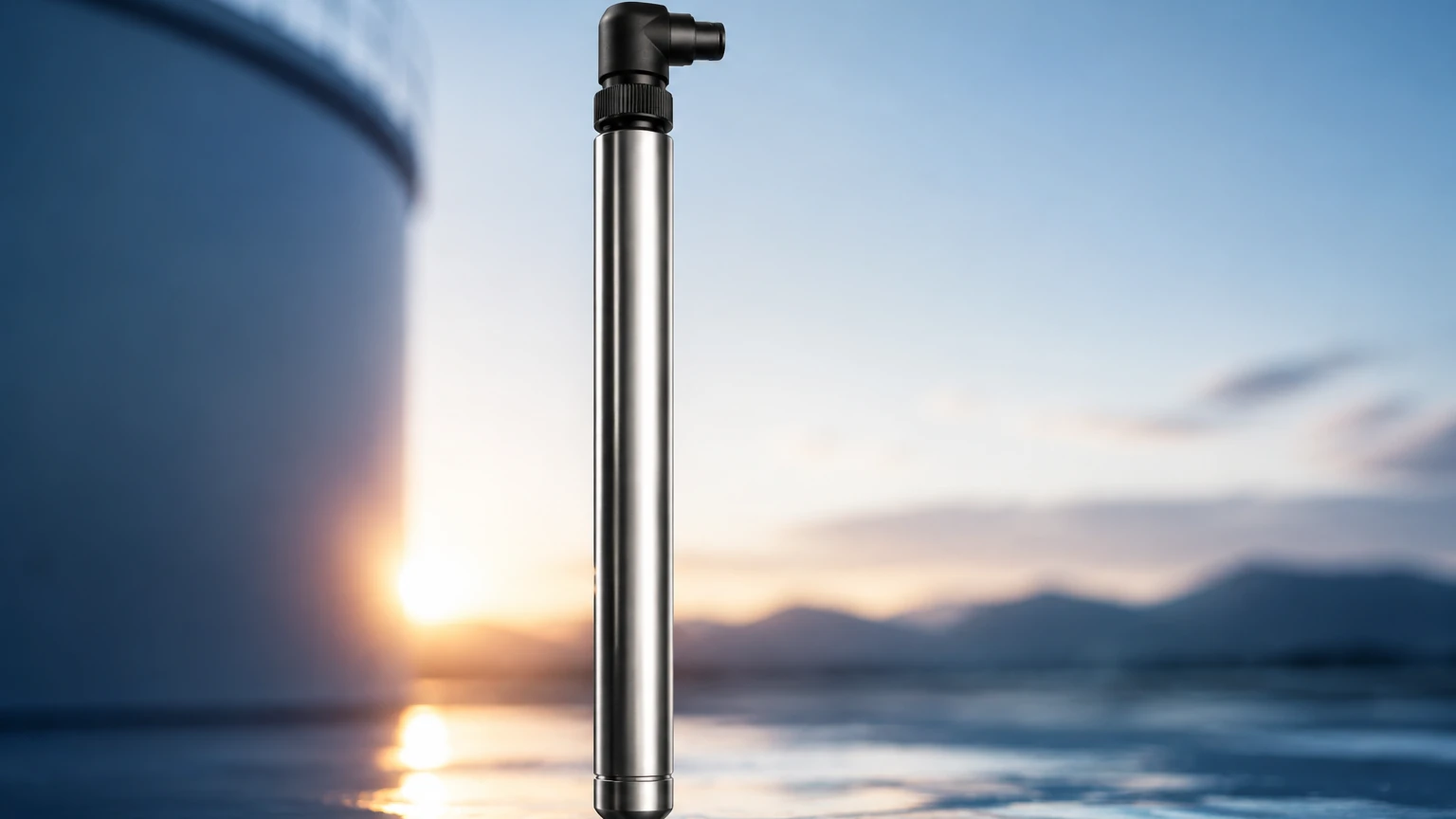
Since many fuels are flammable, sensors must often meet ATEX, IECEx, or UL standards for hazardous locations. This usually involves using intrinsically safe (IS) wiring or explosion-proof (Ex d) housings. Furthermore, for outdoor tanks, the sensor housing should be rated at least IP67 or IP68 to prevent moisture ingress from rain or humidity.
Limitations and Common Risks
While modern fuel level monitoring sensors are highly capable, users must be aware of specific operational risks:
1. Temperature-Induced Expansion: Fuel volume changes with temperature. A tank may contain the same mass of fuel, but the level will rise as the temperature increases. For high-accuracy inventory management, temperature compensation probes should be integrated with the level sensor.
2. Dielectric Constant Variability: Biofuels (like E85 or Biodiesel) have different dielectric constants than pure petroleum products. Capacitance and Radar sensors may require recalibration when switching fuel types to maintain accuracy.
3. Paraffin Wax and Sludge: In cold climates, diesel fuel can develop paraffin wax crystals. In long-term storage, sludge may accumulate at the bottom. These can coat submersible hydrostatic sensors or interfere with float mechanisms, requiring periodic maintenance and cleaning.
Frequently Asked Questions (FAQ)
Q: Can one sensor be used for both diesel and gasoline?
A: Technically, yes, if the sensor is chemically compatible with both. However, because gasoline is much more volatile and has a different density, a hydrostatic or capacitance sensor would need to be recalibrated when switching between the two.
Q: How do I monitor fuel levels in a horizontal cylindrical tank?
A: Horizontal tanks require a non-linear conversion. While the sensor measures height (mm), the volume (liters) does not increase linearly. Most modern transmitters or digital displays allow you to input a strapping table or tank dimensions to calculate the volume automatically.
Q: Is radar better than ultrasonic for fuel?
A: In most industrial fuel applications, yes. Radar is not affected by the fuel vapors that typically accumulate in the headspace of the tank, whereas those vapors can significantly degrade the accuracy of ultrasonic pulses.
Q: How often should a fuel level monitoring sensor be calibrated?
A: For commercial custody transfer or high-accuracy inventory, annual calibration is recommended. For general monitoring or pump protection, a check every two years is usually sufficient, provided there is no significant drift in the readings.
Conclusion
Effective fuel management starts with selecting a sensor that matches the physical properties of the fuel and the mechanical constraints of the storage environment. By understanding the principles of hydrostatic pressure, time-of-flight, and capacitance, engineers can implement systems that reduce waste and improve safety. For those seeking specific hardware specifications or customized measurement solutions, it is advisable to Review product options and application support on the Welk Main Page to ensure the selected instrument meets the necessary industrial standards and accuracy requirements.