Gas Measurement Software
Gas Measurement Software
In modern industrial automation, the precision of gas level and volume monitoring depends as much on the digital processing layer as it does on the physical sensors. Gas measurement software serves as the critical interface between field instrumentation—such as radar level meters or ultrasonic sensors—and the enterprise-level decision-making systems. This software is responsible for converting raw signal data into actionable intelligence, ensuring safety, regulatory compliance, and operational efficiency in sectors ranging from chemical processing to oil and gas storage.
To understand the necessity of specialized software, one must first examine the physical principles of measurement and the complexities inherent in monitoring gaseous media within industrial vessels.
Understanding the Principles of Gas Level and Volume Measurement
Before selecting or configuring gas measurement software, it is essential to understand how level instruments interact with the medium. Gas measurement typically involves monitoring the liquid-gas interface in a pressurized tank or calculating the volume of gas based on vessel geometry and environmental conditions.
Radar Level Measurement (ToF)
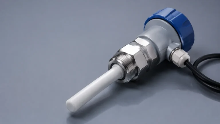
Radar level meters operate on the Time-of-Flight (ToF) principle. The device emits high-frequency electromagnetic pulses (often in the 26 GHz or 80 GHz range) that travel at the speed of light. When these pulses hit the surface of a liquid or a solid within a gas-filled space, they are reflected back to the sensor. The software within the transmitter or a connected PLC calculates the distance based on the time interval between transmission and reception.
In gas applications, radar is preferred because electromagnetic waves are largely unaffected by the temperature, pressure, or vacuum conditions of the gas phase. However, the software must account for the dielectric constant of the material to ensure signal reliability.
Ultrasonic Level Measurement
Ultrasonic sensors use sound waves rather than electromagnetic pulses. The transducer emits an ultrasonic pulse that reflects off the surface of the medium. Unlike radar, the speed of sound is highly dependent on the density and composition of the gas through which it travels. Therefore, gas measurement software for ultrasonic systems must include robust temperature compensation algorithms and, in some cases, pressure correction to maintain accuracy.
Hydrostatic Pressure Measurement
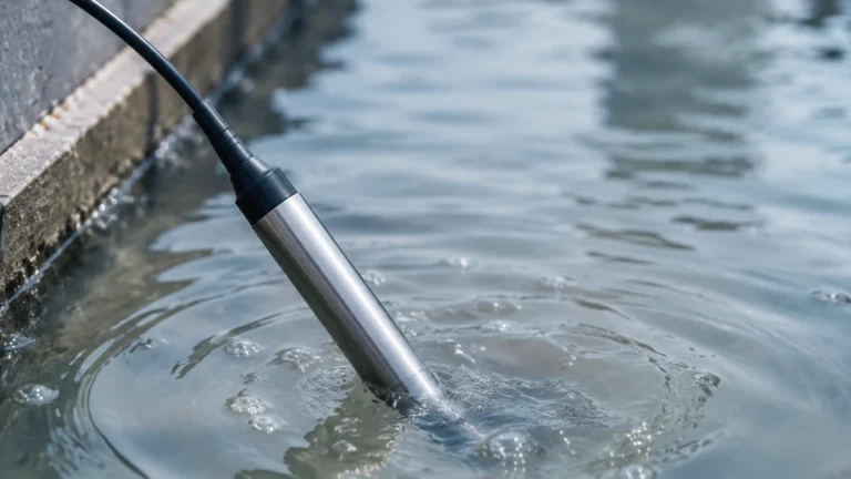
For liquefied gases stored under pressure, hydrostatic transmitters measure the pressure exerted by the liquid column. The software then uses the known density of the gas and liquid to calculate the level. This method requires the software to subtract the top-side gas pressure (vapor pressure) from the total bottom pressure to isolate the liquid level accurately.
The Core Functions of Gas Measurement Software
Industrial gas measurement software is designed to handle the high volatility and environmental sensitivity of gas-related data. Its primary functions include data normalization, volume calculation, and diagnostic monitoring.
Data Acquisition and Normalization
Field instruments often output raw signals via 4-20 mA loops, Modbus RTU, or HART protocols. The software aggregates these signals and normalizes the data. For instance, if a sensor reports a distance of 5.2 meters (17.06 feet) in a tank that is 10 meters (32.8 feet) high, the software calculates the remaining ullage and the current product height.
Compensation Algorithms
Gas volume is highly sensitive to thermal expansion. Advanced software utilizes the Ideal Gas Law ($PV = nRT$) or more complex real-gas equations (such as Peng-Robinson) to provide "Standard Volume" or "Normal Volume" readings. This allows engineers to compare gas quantities across different sites regardless of local temperature or pressure variations.
Tank Strapping and Geometry Mapping
Most industrial tanks are not perfect cylinders. They may have dish bottoms, internal obstructions (agitators, heating coils), or horizontal orientations. Gas measurement software includes "strapping tables" that map the measured level to the actual volume. This ensures that a 10 cm (3.94 inch) rise in level at the bottom of a spherical tank is calculated differently than a 10 cm rise near the center.
Key Selection Criteria for Industrial Applications
When evaluating gas measurement software, technical teams should focus on interoperability, accuracy, and the ability to handle multi-parameter inputs. For a comprehensive look at compatible hardware, engineers can visit the Main Page of industrial instrument providers to review product options and application support.
1. Communication Protocol Compatibility
The software must support the existing infrastructure. Common protocols include:
* HART (Highway Addressable Remote Transducer): Allows digital communication over analog wires.
* Modbus TCP/RTU: The industry standard for PLC and SCADA integration.
* Foundation Fieldbus/Profibus: Used in complex, large-scale plant automation.
2. Real-Time Visualization and Reporting
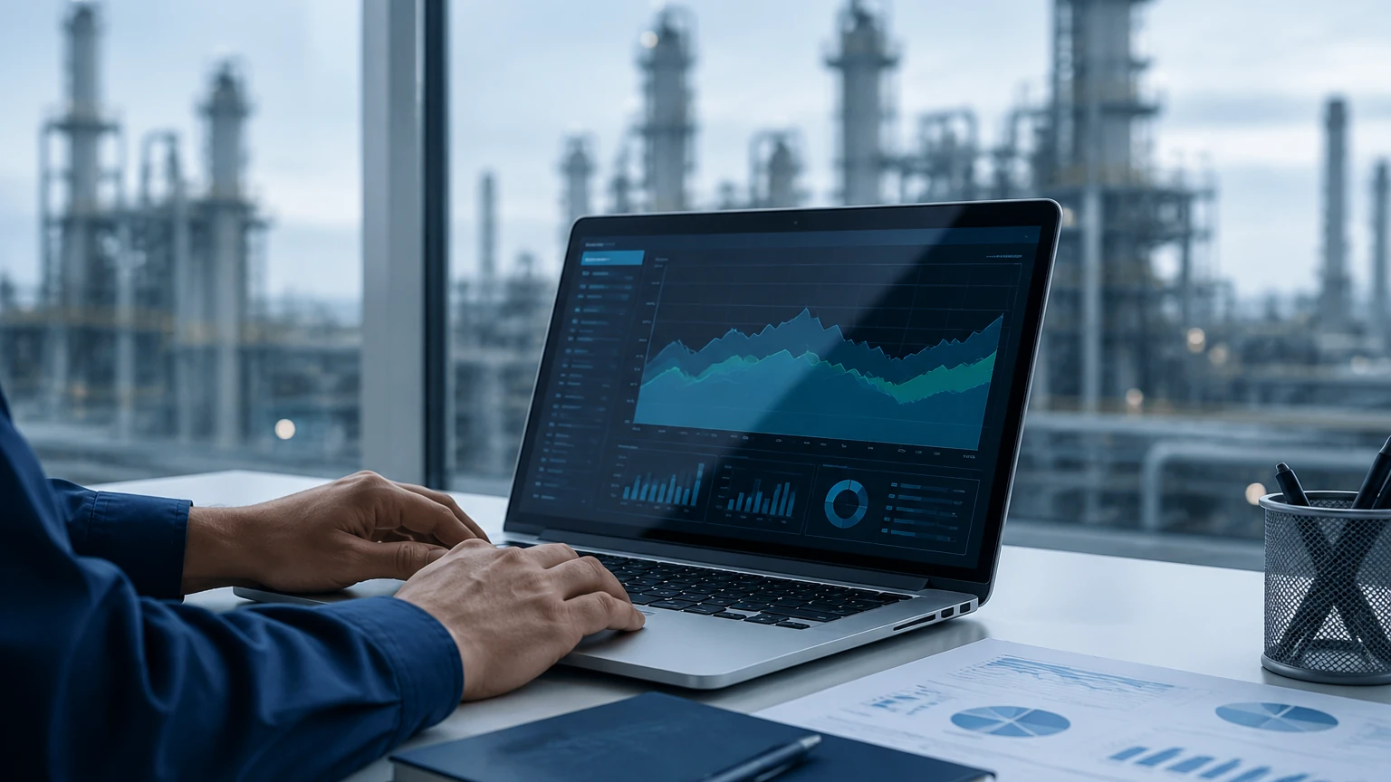
A B2B-grade software solution should provide real-time dashboards showing trend lines, alarm statuses, and historical logs. This is vital for detecting slow leaks or identifying process inefficiencies.
3. Scalability
In a growing industrial facility, the software should be able to integrate new measurement points without requiring a complete system overhaul. This includes support for various sensor types, such as radar, ultrasonic, and magnetic level gauges, simultaneously.
Installation and System Integration Considerations
Successful implementation of gas measurement software requires precise alignment between the physical installation and the digital configuration. Errors during this phase can lead to persistent inaccuracies.
Sensor Calibration and Zero-Point Setting
During installation, the software must be calibrated to the "Zero" and "Full" points of the vessel. For a radar meter, the software must be told exactly where the flange face is located relative to the bottom of the tank. If the sensor is mounted on a nozzle, the software must be configured to ignore reflections from the nozzle walls.
Signal Filtering and False Echo Suppression
Internal tank structures like ladders or pipes can create "ghost" echoes. Modern gas measurement software allows for "False Echo Mapping." The technician runs a scan of the empty tank, and the software records all static reflections. During operation, the software subtracts these static signals, focusing only on the moving echo from the gas-liquid interface.
Network Latency and Update Rates
In high-pressure gas applications, levels can change rapidly. The software must be configured with an appropriate update rate. While a 1-second update might be necessary for process control, a 30-second update might suffice for inventory management to save power in wireless installations.
Comparison of Measurement Technologies and Software Requirements
The following table outlines how different measurement technologies influence the requirements of the accompanying software.
| Technology | Primary Software Requirement | Best Use Case | Sensitivity to Gas Composition |
| :— | :— | :— | :— |
| Radar (80 GHz) | False Echo Mapping | High-precision chemical storage | Low |
| Ultrasonic | Temperature Compensation | Water treatment / Open channels | High |
| Hydrostatic | Differential Pressure Logic | Liquefied Gas (LPG/LNG) | Medium |
| Laser Level | Narrow Beam Processing | Tall, narrow silos | Low |
| Magnetic Gauge | Remote Signal Integration | High-pressure boilers | None (Mechanical) |
Limitations and Operational Risks
While software enhances measurement accuracy, it cannot fully compensate for poor hardware selection or extreme environmental conditions.
* Vapor and Condensation: Heavy steam or chemical vapors can attenuate ultrasonic signals. While radar is more resistant, heavy condensation on the antenna can still cause signal drift. Software diagnostics should be set to alert operators when signal strength drops below a certain decibel (dB) threshold.
* Turbulence and Foam: Rapid filling or agitation can create surface foam. Foam often absorbs radar and ultrasonic pulses, leading to a "Loss of Echo." The software must be programmed with safety logic to hold the last valid reading or trigger an alarm rather than reporting a random value.
* Cybersecurity: As gas measurement software becomes more connected to cloud platforms, the risk of unauthorized access increases. Systems should utilize encrypted protocols and multi-level user permissions to protect critical process data.
Frequently Asked Questions (FAQs)
Q: Can gas measurement software calculate mass instead of just volume?
A: Yes, provided the software receives data from a pressure transmitter and a temperature sensor. By integrating the density of the specific gas (often stored in a built-in library), the software can calculate the mass of the gas in real-time.
Q: How does software handle different tank shapes?
A: Most professional software packages include a library of standard tank shapes (cylindrical, spherical, elliptical). For custom vessels, users can upload a strapping table (a CSV or Excel file) that correlates height increments to specific volumes.
Q: Is it possible to update the software without stopping the process?
A: In most modern SCADA and PLC environments, the monitoring software can be updated or reconfigured while the instruments are live. However, any changes to the scaling or calibration factors should be done during a scheduled maintenance window to avoid triggering false alarms in the control system.
Q: What is the difference between "Standard" and "Actual" volume in the software?
A: "Actual" volume is the space the gas occupies at current temperature and pressure. "Standard" volume is a calculated value representing what that volume would be at standard conditions (typically 15°C/60°F and 1 atm). This is crucial for billing and custody transfer.
Conclusion
Selecting the right gas measurement software is a foundational step in achieving precise industrial level control. By understanding the underlying physics of radar and ultrasonic measurement, and by ensuring the software is correctly configured for tank geometry and environmental compensation, engineers can significantly reduce measurement uncertainty. For those seeking to upgrade their field instrumentation or integrate new software solutions, consulting the Main Page of a dedicated manufacturer provides the technical specifications necessary to ensure system compatibility and long-term reliability.