Grain Level Indicator
Grain Level Indicator
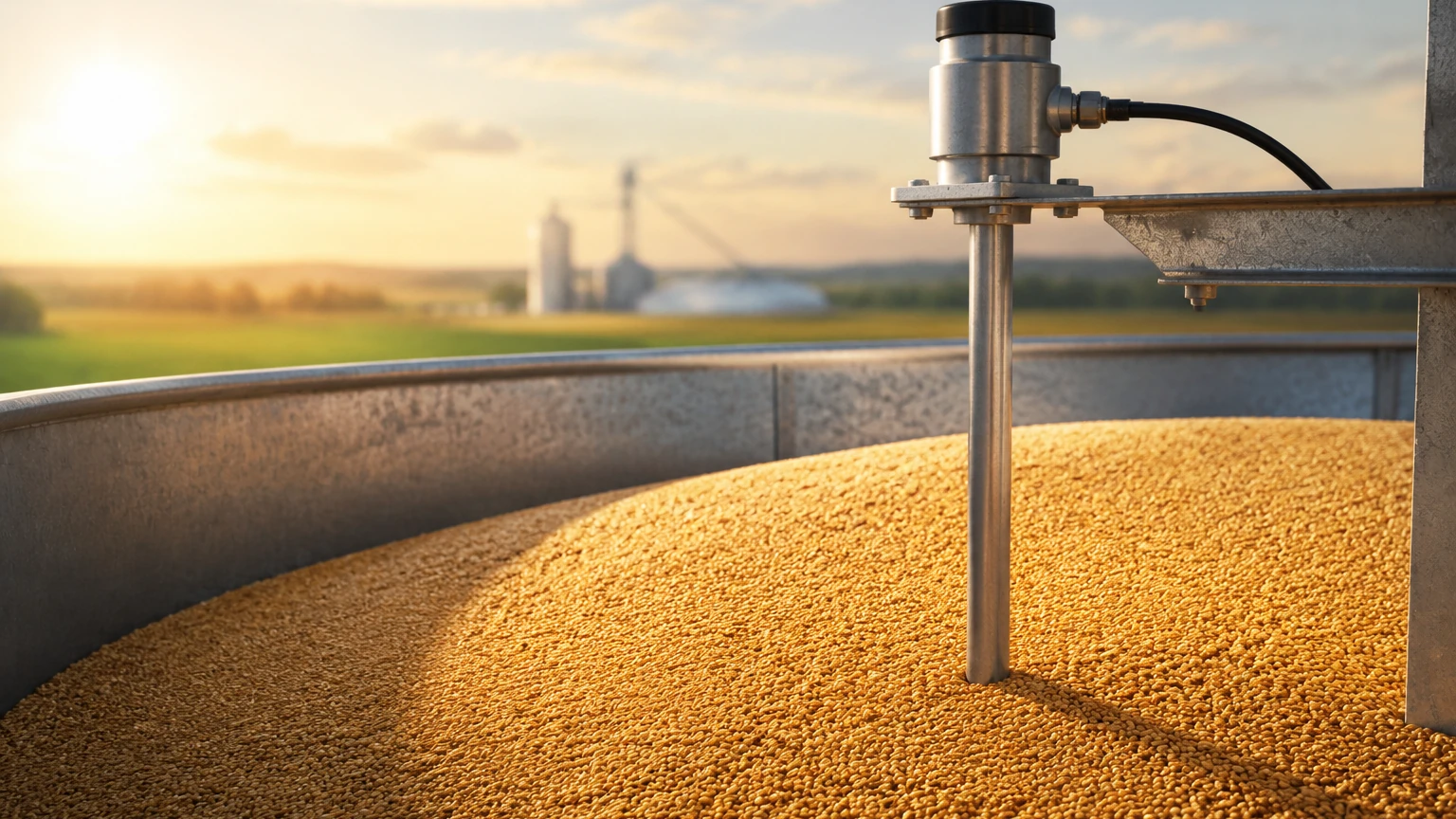
In the agricultural and bulk solids processing industries, a grain level indicator is an essential component for inventory management, process automation, and safety. Monitoring the volume of grain—whether it be wheat, corn, rice, or soybeans—within a silo or storage bin requires specialized instrumentation capable of handling high-dust environments, uneven material surfaces, and varying moisture levels. Choosing the correct technology ensures that facilities avoid overfilling, optimize storage capacity, and maintain consistent supply chains.
Measurement Principles for Grain Level Indicators
Before selecting a specific grain level indicator, it is vital to understand the physical principles that govern how these sensors interact with bulk solids. Grain measurement typically falls into two categories: point level detection and continuous level measurement.
1. Non-Contact Radar (FMCW)
Frequency Modulated Continuous Wave (FMCW) radar is the gold standard for grain measurement. These sensors emit a continuous signal with a changing frequency. The difference between the transmitted and received frequencies is proportional to the distance to the grain surface. Modern 80GHz radar sensors are particularly effective because their high frequency allows for a very narrow beam angle, which avoids interference from silo walls or internal structures like ladders and braces.
2. Ultrasonic Measurement
Ultrasonic sensors function by emitting sound pulses that reflect off the grain surface. The time-of-flight (ToF) between emission and reception determines the distance. While cost-effective, ultrasonic technology is often challenged in grain applications due to high dust concentrations, which can attenuate the sound signal, and noise generated during pneumatic filling processes.
3. Guided Wave Radar (GWR)
GWR utilizes a probe or cable that extends into the grain. A low-energy microwave pulse travels down the probe and reflects when it hits the grain (which has a different dielectric constant than air). This method is highly accurate and unaffected by dust, but the physical cable is subject to significant tensile forces as the grain settles or is discharged.
4. Mechanical Point Level Indicators
For simple high-level or low-level alerts, mechanical switches like rotary paddles are common. A motor slowly rotates a paddle; when grain reaches the paddle, the rotation is impeded, triggering a microswitch. These are robust but provide no information about the intermediate volume of the silo.
Point Level vs. Continuous Monitoring
Industrial grain management usually requires a combination of both point level and continuous measurement technologies to ensure redundancy and accuracy.
* Continuous Monitoring: Essential for real-time inventory tracking. Technologies like radar or ultrasonic provide a 4-20mA or digital signal (Modbus, Hart) representing the exact level from 0% to 100%. This is critical for large-scale operations where knowing the exact tonnage is necessary for logistics and sales.
* Point Level Detection: Often used as a safety backup. A rotary paddle or vibrating level switch is installed at the very top of the silo to act as a high-level alarm. If the continuous sensor fails or is miscalibrated, the point level switch provides a hard-wired stop signal to the filling conveyor to prevent a catastrophic overspill.
Technical Challenges in Grain Applications
Grain is a difficult medium to measure compared to liquids. Engineers must account for several variables when specifying a grain level indicator:
* Angle of Repose: Unlike liquids, which maintain a horizontal surface, grain forms a cone when filled and an inverted cone when emptied. This "angle of repose" can lead to measurement errors if the sensor is not positioned correctly. Advanced radar sensors often include software algorithms to average the surface profile.
* Dust and Particulates: Grain handling is inherently dusty. Dust can coat sensor faces or block acoustic signals. Radar is generally immune to dust, whereas ultrasonic sensors may require self-cleaning faces or air purging.
* Dielectric Constant (εr): Radar depends on the dielectric constant of the material to reflect the signal. Grains generally have low dielectric constants (ranging from 2.0 to 5.0). Lower dielectric values result in weaker signal reflections, requiring sensors with high sensitivity and sophisticated signal processing.
* Mechanical Stress: In tall silos (e.g., 30 meters or 100 feet), the downward pull of the grain (friction) on any submerged probe—such as a Guided Wave Radar cable—can reach several tons. If the silo structure or the sensor mounting is not designed for these loads, the sensor may be ripped from the roof.
Practical Selection Table
| Technology | Accuracy | Dust Resistance | Maintenance | Best Use Case |
| :— | :— | :— | :— | :— |
| 80GHz Radar | ±2 mm | Excellent | Low | Large silos, high-accuracy inventory |
| Ultrasonic | ±10 mm | Moderate | Moderate | Small bins, low-dust environments |
| Guided Wave Radar | ±5 mm | Excellent | High (Stress) | Narrow bins with low dielectric grain |
| Rotary Paddle | N/A (Point) | High | Moderate | High/Low level safety alarms |
| Capacitance | N/A (Point) | High | Low | Small hoppers, feed bins |
Installation Considerations
Proper installation is as important as selecting the right technology. When installing a grain level indicator, follow these engineering guidelines:
1. Mounting Position: Avoid mounting the sensor in the center of the silo if the filling inlet is also in the center. The filling stream will interfere with the signal. Conversely, do not mount too close to the wall, as the beam may reflect off the wall or internal supports. A common rule of thumb is to mount the sensor at 1/6th to 1/3rd of the silo diameter from the wall.
2. Beam Angle: Ensure the sensor's beam has a clear path to the grain. For radar, a narrow beam (e.g., 3° to 8°) is preferred to avoid internal obstructions.
3. Aiming Flanges: Because of the angle of repose, using an adjustable aiming flange allows the technician to point the sensor toward the middle of the grain slope, maximizing the returned signal strength.
4. Nozzle Height: If the sensor is mounted on a nozzle, the nozzle should be as short as possible. If the nozzle is too long, the signal may reflect off the inside of the nozzle before reaching the grain, creating a "dead zone" at the top of the measurement range.
Limitations and Common Risks
While modern instrumentation is highly reliable, certain risks remain in grain storage environments. Moisture content is a primary factor; if grain is stored with high moisture, it may clump or stick to the silo walls (bridging). In these cases, a sensor may report that the silo is full even if the center has been emptied.
Furthermore, grain dust is often explosive (ATEX/IECEx zones). Any grain level indicator installed in a silo must be appropriately rated for hazardous dust environments (e.g., Class II, Div 1). Using a non-rated sensor is a significant safety violation and a fire hazard.
For more detailed technical specifications and product comparisons, you can visit the Main Page to review various industrial instrumentation options.
Frequently Asked Questions (FAQ)
Q: Can I use an ultrasonic sensor for flour or very fine grain dust?
A: It is generally not recommended. Fine dust significantly attenuates sound waves. For flour or fine powders, 80GHz radar is a much more reliable choice as it penetrates dust clouds without signal loss.
Q: How do I handle the "pulling force" on a Guided Wave Radar cable?
A: You must calculate the maximum tensile load based on the silo height and grain type. Ensure the silo roof is reinforced and the sensor is equipped with a heavy-duty cable and a high-load mounting nut. In many cases, non-contact radar is preferred specifically to avoid these mechanical stresses.
Q: Does the moisture content of the grain affect radar accuracy?
A: Moisture increases the dielectric constant of the grain, which actually makes the radar signal reflection stronger. However, if moisture causes the grain to stick to the sensor face, it may cause a false reading. Most high-end radars use a PTFE or PEEK lens to prevent material buildup.
Q: What is the maximum range for a grain level indicator?
A: Modern radar level meters can measure distances up to 120 meters (approx. 393 feet), which is more than sufficient for even the largest industrial grain terminals.
Conclusion
Selecting a grain level indicator requires a balance between budget, accuracy requirements, and the physical constraints of the storage vessel. While mechanical switches provide essential safety backups, continuous 80GHz radar has become the industry standard for reliable inventory management due to its ability to ignore dust and provide precise data regardless of the material's surface profile. For engineering support in selecting the right sensor for your specific application, reviewing technical data on the Main Page of the manufacturer's site is a recommended next step.