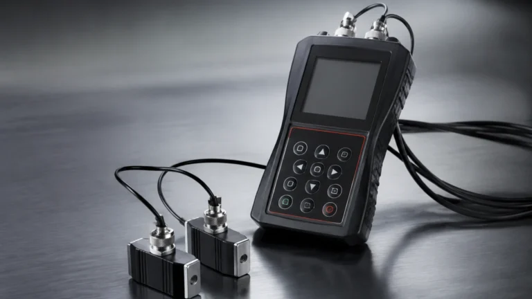
High Pressure Transducer
High Pressure Transducer
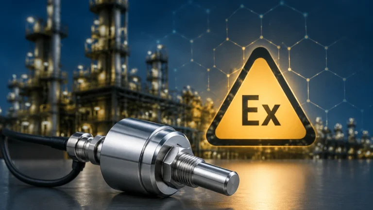
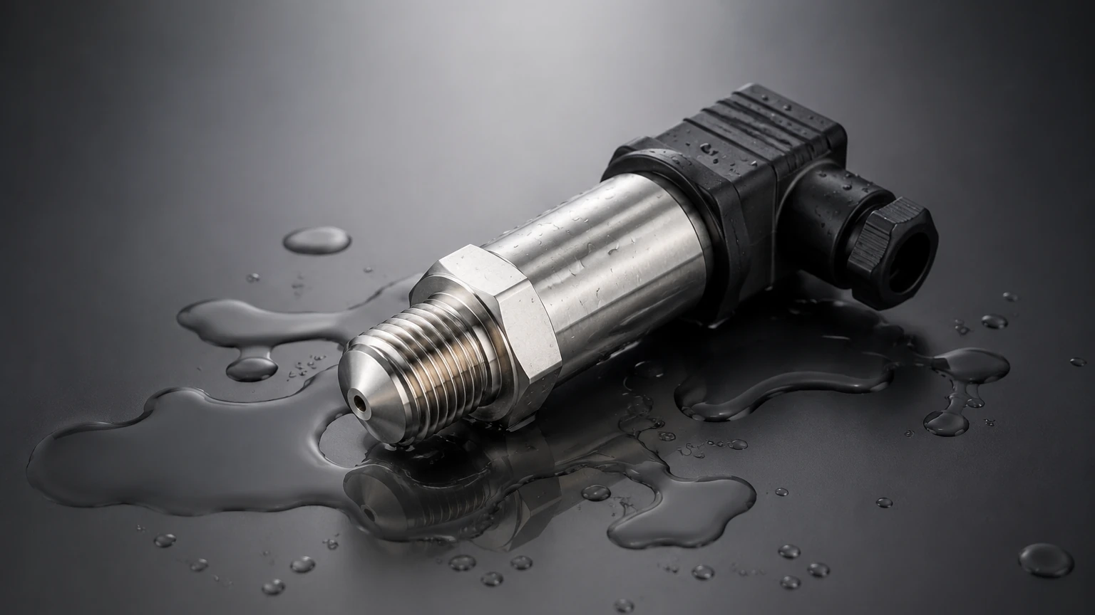
In the landscape of industrial automation and process control, the high pressure transducer serves as a fundamental component for monitoring and managing fluid dynamics. These devices are engineered to convert mechanical pressure into a measurable electrical signal, typically in environments where standard sensors would fail due to structural stress or signal instability. For engineers and procurement professionals, understanding the technical nuances of these instruments is essential for ensuring the safety, accuracy, and longevity of high-pressure systems.
High pressure transducers are distinct from standard pressure sensors due to their robust construction and specialized sensing elements. They are frequently deployed in hydraulic systems, oil and gas extraction, chemical processing, and specialized level measurement applications where hydrostatic pressure exceeds typical atmospheric or low-pressure thresholds. This article explores the principles, selection criteria, and practical implementation of these critical instruments.
Measurement Principles of High Pressure Transducers
To select the correct instrument, one must first understand the underlying physics that allow a transducer to function under extreme loads. Most high pressure transducers utilize one of three primary sensing technologies: piezoresistive, thin-film strain gauge, or capacitive sensing.
Piezoresistive Sensing
Piezoresistive transducers utilize a semiconductor material, often silicon, which changes its electrical resistance when subjected to mechanical strain. In a high-pressure configuration, the silicon element is usually protected by a stainless steel or specialized alloy diaphragm. The pressure is transmitted through a fill fluid (such as silicone oil) to the sensor. This technology is known for its high sensitivity and fast response times, though it requires careful temperature compensation as silicon is naturally sensitive to thermal fluctuations.
Thin-Film Strain Gauge
For extremely high pressures—often exceeding 1,000 bar (14,500 psi)—thin-film strain gauges are the industry standard. In this design, the resistive material is sputtered directly onto a metal diaphragm using a vacuum deposition process. Because there is no organic adhesive or fill fluid involved, these sensors offer exceptional long-term stability and resistance to pressure cycles. They are particularly effective in hydraulic applications where rapid pressure spikes (water hammer) are common.
Capacitive Sensing
Capacitive transducers measure the change in electrical capacitance between a flexible diaphragm and a fixed backplate. While less common in ultra-high pressure ranges compared to strain gauges, they are highly valued for their accuracy and ability to withstand significant overpressure without permanent damage. They are often used in differential pressure applications where the static line pressure is very high.
Application in Industrial Level Measurement
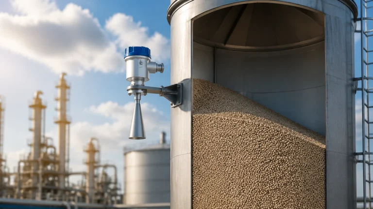
While pressure measurement is the primary function, the high pressure transducer is a vital tool for level measurement in pressurized vessels. This is achieved through the principle of hydrostatic pressure.
In an open tank, the level is directly proportional to the pressure at the bottom ($P = \rho gh$). However, in high-pressure environments such as steam boilers or chemical reactors, the vessel is sealed and contains a pressurized gas blanket. To accurately measure the liquid level, a high pressure transducer must be used in a differential configuration or as part of a dual-sensor system.
The transducer measures the total pressure at the bottom of the vessel, and the gas pressure at the top is subtracted to isolate the pressure exerted by the liquid column. Because these vessels often operate at pressures of 100 bar (1,450 psi) or higher, the transducer must be rated for the maximum possible system pressure while still maintaining the sensitivity required to detect small changes in liquid height.
Technical Selection Criteria
Choosing the right high pressure transducer requires a detailed analysis of the process conditions. The following table provides a comparison of key factors to consider during the evaluation process.
| Criteria | Specification Detail | Importance |
| :— | :— | :— |
| Pressure Range | 0-600 bar to 0-5,000+ bar | Must exceed maximum operating pressure by a safety margin. |
| Accuracy (FS) | 0.1%, 0.25%, or 0.5% | Determines the precision of the process control loop. |
| Output Signal | 4-20mA, 0-10V, RS485/HART | Compatibility with PLC or DCS infrastructure. |
| Wetted Materials | 316L SS, Hastelloy, Titanium | Resistance to corrosive media or hydrogen embrittlement. |
| Temperature Range | -40°C to +125°C (standard) | High-temperature versions required for steam or molten polymers. |
| Ingress Protection | IP65, IP67, or IP68 | Protection against moisture, dust, and wash-down cycles. |
Material Compatibility
In high-pressure environments, material fatigue and chemical attack are accelerated. For hydrogen applications, specialized materials are required to prevent hydrogen embrittlement, which can lead to catastrophic diaphragm failure. For seawater or acidic environments, alloys like Inconel or Monel are preferred over standard stainless steel.
For more information on specific material options and instrument configurations, you can visit the Main Page to review product options and application support.
Installation and Maintenance Considerations
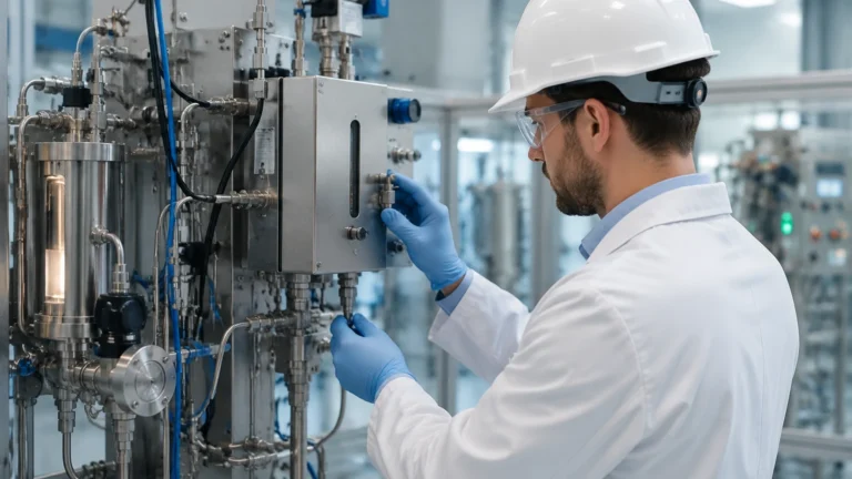
The performance of a high pressure transducer is heavily dependent on proper installation. High-pressure systems pose unique risks, and the following guidelines should be followed:
1. Pressure Ports and Sealing: High-pressure connections often use specialized threading, such as Autoclave or high-pressure NPT. Ensure that the sealing material (O-rings or metal-to-metal seals) is rated for the maximum system pressure.
2. Impulse Lines: When measuring level in high-pressure tanks, the impulse lines connecting the tank to the transducer should be sloped to prevent gas pockets (in liquid lines) or liquid traps (in gas lines) from causing measurement errors.
3. Snubbers and Pulsation Dampeners: If the system is subject to rapid pressure fluctuations or hydraulic shocks, a pressure snubber should be installed to protect the transducer diaphragm from mechanical fatigue.
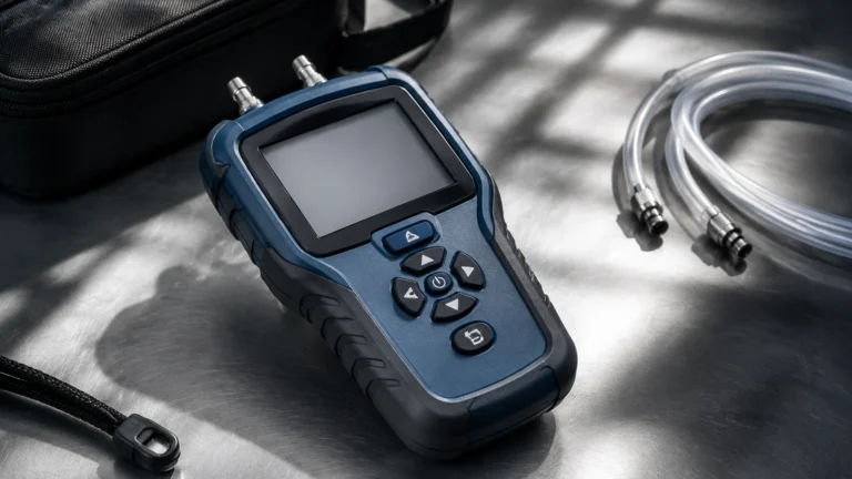
4. Zero-Point Calibration: High pressure transducers may experience a slight zero-shift after installation due to mounting torque or static line pressure. A field calibration or zero-adjustment should be performed once the system is at its baseline state.
5. Thermal Isolation: If the process fluid is extremely hot, use a siphon or capillary tube to ensure the temperature at the transducer remains within its compensated operating range.
Operational Limitations and Risks
Despite their robust design, high pressure transducers are not indestructible. Engineers must be aware of the following limitations:
* Overpressure Limits: Every transducer has a proof pressure (the maximum pressure without permanent calibration shift) and a burst pressure (the pressure at which the housing fails). Exceeding the proof pressure can lead to non-linear readings and permanent damage.
* Fatigue Life: In applications with frequent pressure cycling (e.g., high-speed hydraulic presses), the metal diaphragm will eventually fatigue. It is important to select a sensor designed for high-cycle life and to implement a regular replacement schedule.
* Signal Noise: In high-pressure industrial environments, electromagnetic interference (EMI) from large motors or variable frequency drives (VFDs) can degrade the transducer signal. Using shielded cables and 4-20mA current loops helps mitigate this risk.
Frequently Asked Questions (FAQs)
What is the difference between a high pressure transducer and a pressure transmitter?
In technical terms, a transducer typically provides a raw voltage output (e.g., 0-100mV), while a transmitter includes signal conditioning circuitry to provide a standardized current or voltage output (e.g., 4-20mA). However, in many B2B contexts, the terms are used interchangeably.
How often should a high pressure transducer be calibrated?
Most manufacturers recommend an annual calibration. However, in critical safety applications or environments with high vibration and pressure cycling, semi-annual or quarterly checks may be necessary to ensure continued accuracy.
Can these sensors be used for both liquid and gas?
Yes, provided the wetted materials are compatible with both media. However, users must account for the different behaviors of compressible gases versus incompressible liquids, especially regarding response time and safety in the event of a leak.
What happens if the diaphragm ruptures?
In high-pressure applications, a diaphragm rupture can be dangerous. Many high-pressure sensors are designed with a "secondary containment" or a blow-out disk to vent the pressure safely away from the electrical housing and personnel.
Conclusion
The high pressure transducer is an indispensable tool for modern industrial processes, providing the data necessary to maintain safety and efficiency in demanding environments. By understanding the measurement principles—from piezoresistive to thin-film technologies—and carefully evaluating factors like material compatibility and overpressure ratings, engineering teams can select the most cost-effective and reliable solution.
Proper installation, including the use of snubbers and correct sealing techniques, further ensures that these instruments provide accurate data over a long service life. For those seeking to optimize their level and pressure measurement systems, consulting with a professional manufacturer like Welk provides access to the customized OEM/ODM services and technical expertise required for complex industrial automation challenges. To explore the full range of available instrumentation, visit the Main Page for detailed specifications and technical support.