High Temperature Oxygen Sensor
High Temperature Oxygen Sensor
In the landscape of industrial process control, the high temperature oxygen sensor stands as a critical component for optimizing combustion, ensuring product quality, and maintaining environmental compliance. These sensors are engineered to operate in environments where temperatures frequently exceed 600°C (1,112°F), providing real-time data on oxygen concentration in flue gases, melting furnaces, and chemical reactors. For engineers and plant managers, understanding the technical nuances of these instruments is essential for achieving operational efficiency and safety.
While oxygen monitoring focuses on gas composition, it is often paired with other critical process parameters. In many industrial settings, such as power generation or chemical processing, gas analysis is used in tandem with robust level measurement solutions to ensure that fuel supplies and chemical reagents are managed effectively. For a broader look at primary process instrumentation, engineers often refer to the Main Page of specialized manufacturers to integrate comprehensive monitoring systems.
Measurement Principles of High Temperature Oxygen Sensors
The vast majority of high temperature oxygen sensors utilize the Zirconium Dioxide (ZrO2) principle, often referred to as a Zirconia sensor. This technology relies on the properties of solid electrolytes at elevated temperatures.
The Zirconia Solid Electrolyte Principle
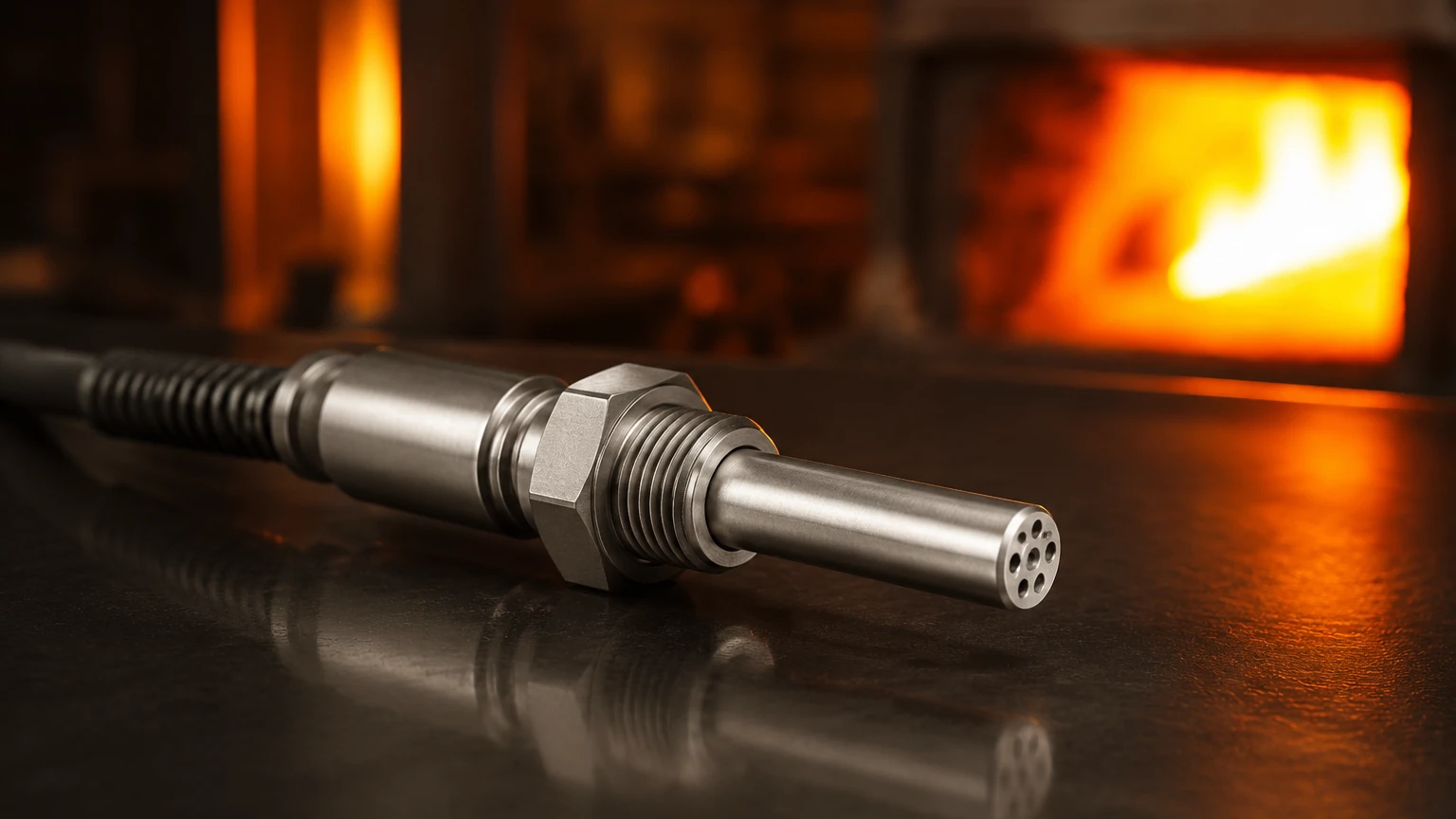
Zirconium dioxide, when stabilized with yttrium oxide (yttria), becomes a conductor of oxygen ions at temperatures above approximately 600°C. The sensor typically consists of a ceramic tube or disc coated on both sides with a thin layer of porous platinum, which acts as an electrode.
When there is a difference in oxygen partial pressure between the two sides of the zirconia element (usually one side is exposed to a reference gas, like ambient air, and the other to the process gas), oxygen ions move through the crystal lattice. This movement creates an electrical potential (EMF) across the electrodes. This phenomenon is governed by the Nernst Equation:
E = (RT / 4F) × ln(P1 / P2)
Where:
* E is the electromotive force (Volts).
* R is the gas constant.
* T is the absolute temperature (Kelvin).
* F is Faraday's constant.
* P1 is the partial pressure of oxygen in the reference gas.
* P2 is the partial pressure of oxygen in the process gas.
Because the output voltage is logarithmic relative to the oxygen concentration, these sensors are exceptionally sensitive at low oxygen levels (e.g., in the parts-per-million range), making them ideal for combustion control where near-stoichiometric conditions are desired.
Key Evaluation Criteria for Industrial Selection
Selecting the right high temperature oxygen sensor requires an analysis of the specific process conditions. Unlike standard gas sensors, high-temperature variants must withstand thermal cycling, corrosive atmospheres, and mechanical stress.
1. Temperature Range and Stability
Standard industrial high-temperature sensors are designed for continuous operation between 600°C and 1,400°C. It is vital to confirm whether the sensor requires an internal heater (to maintain the zirconia element at its conductive temperature) or if it relies on the process heat itself. In applications with fluctuating temperatures, a heated probe is often preferred to maintain a stable calibration.
2. Probe Construction and Materials
In corrosive environments, such as those found in glass manufacturing or waste incineration, the choice of protective sleeve material is paramount. Common materials include:
* Stainless Steel (316L/310): Suitable for lower-end "high" temperatures and non-corrosive flue gases.
* Inconel or Hastelloy: Used for high-strength requirements and resistance to oxidation.
* Ceramic (Alumina/Silicon Carbide): Necessary for temperatures exceeding 1,100°C or in highly abrasive/corrosive gas streams.
3. Response Time
In dynamic combustion processes, the speed at which a sensor detects a change in oxygen levels can impact the efficiency of the control loop. In-situ sensors (placed directly in the gas stream) generally offer faster response times (typically <5 seconds) compared to extractive systems that must pump gas to a remote sensor.
Practical Selection Table
| Feature | In-Situ Zirconia Probe | Extractive Sampling System | Wide-Band (Pump-Cell) Sensor |
| :— | :— | :— | :— |
| Max Temperature | Up to 1,400°C (with ceramic sleeve) | Process temp independent (gas is cooled) | Typically up to 900°C |
| Response Time | Very Fast (1-3 seconds) | Slow (10-30+ seconds) | Fast |
| Maintenance | Low (no moving parts) | High (filters, pumps, coolers) | Moderate |
| Accuracy | High at low O2 levels | High across wider ranges | Very High (linear output) |
| Typical Use | Flue gas, Boilers, Kilns | High-dust or high-moisture gas | Automotive testing, Lean-burn engines |
Installation and Engineering Considerations
Proper installation is the single most important factor in ensuring the longevity and accuracy of a high temperature oxygen sensor. Engineering teams should follow a strict checklist during the design phase.
Positioning and Orientation
The probe should be installed in a location where the gas is well-mixed and representative of the process. Avoid "dead zones" or areas near air leaks (such as damper seals), as these will provide false high-oxygen readings. In horizontal ducts, the probe is ideally installed horizontally or at a slight downward angle to prevent condensate from pooling on the ceramic element, which could cause thermal shock and cracking.
Thermal Shock Prevention
Zirconia elements are brittle. When inserting a probe into a hot process, it must be pre-heated or inserted slowly to allow the ceramic components to expand gradually. Similarly, if the process involves rapid cooling cycles, specialized "thermal-shock resistant" ceramic tips should be specified.
Reference Air Supply
Most zirconia sensors require a reference gas, typically clean, dry instrument air (20.9% O2). The reference air must be free of oil and moisture; contaminants in the reference air will directly lead to measurement errors and may damage the platinum electrodes.
Common Risks and Limitations
While robust, high temperature oxygen sensors are susceptible to specific failure modes that engineers must mitigate.
* Sensor Poisoning: Certain chemicals can "poison" the platinum electrodes, reducing their catalytic activity. Common culprits include silicones, lead, phosphorus, and high concentrations of sulfur. If these are present in the process, specialized filter coatings or extractive systems with scrubbing may be required.
* Reducing Atmospheres: In processes with very low oxygen (reducing conditions), the sensor may be subjected to "blackening." This occurs when oxygen is stripped from the zirconia crystal lattice itself, leading to permanent damage. High-quality sensors include protective measures or specific operating modes for reducing environments.
* Pressure Sensitivity: Since the sensor measures partial pressure, changes in total process pressure will affect the reading. In pressurized boilers or reactors, pressure compensation must be integrated into the signal processing electronics.
The Role of Integrated Instrumentation
In heavy industry, a high temperature oxygen sensor is rarely used in isolation. It is part of a broader ecosystem of process monitoring. For example, in a large industrial boiler, oxygen sensors control the air-to-fuel ratio, while level meters monitor the water levels in the steam drum and the fuel levels in storage tanks.
Reliability across all these points is critical. For instance, a failure in level measurement can lead to dry-firing or overflow, both of which are catastrophic regardless of how well the oxygen levels are managed. Professionals looking for reliable level measurement components to complement their gas analysis systems often visit the Main Page to explore radar, ultrasonic, and hydrostatic options designed for industrial automation.
Frequently Asked Questions (FAQ)
Q: How often should a high temperature oxygen sensor be calibrated?
A: Most industrial systems support "auto-calibration" using a known span gas. For critical combustion processes, a daily or weekly automatic check is common. A full manual calibration with certified gases should be performed every 6 to 12 months, depending on the stability of the environment.
Q: Can these sensors measure oxygen in a vacuum?
A: Standard zirconia sensors require a reference gas at a known pressure. While they can function in low-pressure environments, the Nernst Equation calculation becomes more complex, and specialized vacuum-rated sensors are typically recommended.
Q: What is the typical lifespan of a zirconia element?
A: In clean combustion (e.g., natural gas), a sensor can last 3 to 5 years. In harsh environments like coal-fired boilers or glass furnaces, the lifespan may be reduced to 12 to 24 months due to electrode erosion or ceramic degradation.
Maintenance Guidance
To maximize the ROI of a high temperature oxygen sensor, a proactive maintenance schedule is necessary. This includes:
1. Filter Inspection: For probes equipped with flame arrestors or dust filters, check for plugging which can increase response time.
2. Electrode Resistance Checks: Monitoring the internal impedance of the zirconia cell can provide an early warning of sensor aging before it fails.
3. Reference Air Flow: Ensure the reference air pump or regulator is delivering a consistent, clean flow of air to the internal side of the sensor.
By adhering to these engineering principles and selection criteria, industrial facilities can ensure that their high temperature oxygen sensors provide the accurate, reliable data required for modern process optimization.