How Does a Coriolis Mass Flow Meter Work
How Does a Coriolis Mass Flow Meter Work
In the landscape of industrial process control, the ability to measure fluid flow with high precision is critical for quality assurance, safety, and economic efficiency. Among the various technologies available, the Coriolis mass flow meter stands out as one of the most accurate and versatile instruments. Unlike volumetric flow meters, which measure the space a fluid occupies, a Coriolis meter measures the actual mass passing through the system. This distinction is vital in industries where temperature and pressure fluctuations can significantly alter fluid density.
Understanding how does a coriolis mass flow meter work requires a look into the fundamental physics of motion and inertia. This guide provides a detailed technical overview of the measurement principles, mechanical design, and practical application of these instruments within modern industrial automation frameworks.
The Physics of the Coriolis Principle
The operation of a Coriolis mass flow meter is based on the Coriolis effect, an inertial force described by the French physicist Gaspard-Gustave de Coriolis in 1835. In a rotating system, an object moving in a straight path appears to follow a curved trajectory when viewed from within the rotating frame. In the context of a flow meter, this rotation is replaced by a high-frequency vibration.
The Vibrating Tube Mechanism
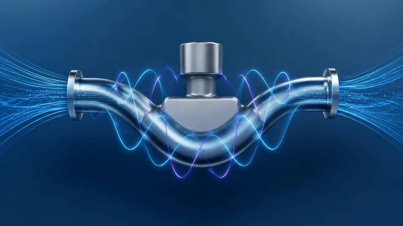
Inside the meter, the fluid passes through one or two measuring tubes. An electromagnetic drive coil causes these tubes to vibrate at their natural resonant frequency, much like a tuning fork. When there is no flow, the tubes vibrate in a uniform, symmetrical manner. Both the inlet and outlet sides of the tube reach the peak of their oscillation cycle at the exact same time.
Introduction of Mass Flow
When a fluid (liquid or gas) begins to flow through the vibrating tubes, the Coriolis force comes into play. As the fluid moves toward the point of maximum vibration (the center of the tube loop), it resists being pushed upward by the tube's motion, exerting a downward force. Conversely, as the fluid moves away from the center toward the outlet, it resists the tube's downward movement, exerting an upward force.
This opposing force on the inlet and outlet sides causes the measuring tube to twist or "lag" on one side and "lead" on the other. This phenomenon is known as a phase shift. The magnitude of this twist is directly proportional to the mass flow rate of the fluid. Because mass is a fundamental property that does not change with temperature or pressure, the measurement remains inherently stable regardless of process conditions.
Internal Components and Sensing Mechanisms
To translate physical vibration into digital data, a Coriolis mass flow meter relies on several high-precision components working in tandem.
1. The Flow Tubes: These are typically made of stainless steel, Hastelloy, or titanium. They can be U-shaped, curved, or straight, depending on the application requirements regarding pressure drop and drainability.
2. Drive Coil: Located at the center of the tube assembly, it receives an oscillating current from the transmitter to maintain the tube's vibration.
3. Pick-off Sensors: Electromagnetic sensors (usually two) are located at the inlet and outlet sections of the tube. They detect the position of the tube over time, generating a sine wave signal.
4. Temperature Sensor (RTD): An internal Resistance Temperature Detector measures the tube temperature to compensate for changes in material elasticity, ensuring accuracy across a wide thermal range.
5. Transmitter: The "brain" of the unit, which processes the sine wave signals from the pick-off sensors, calculates the phase shift, and converts it into a standardized output (such as 4-20mA, HART, or Modbus).
Dual-Parameter Measurement: Density and Temperature
One of the primary advantages of this technology is its ability to measure more than just flow. Because the tubes vibrate at their resonant frequency, the meter can also determine the density of the fluid.
* Density Measurement: The resonant frequency of the tube depends on the total mass of the tube and the fluid inside it. A denser fluid increases the total mass, which lowers the vibration frequency. By monitoring this frequency, the meter provides real-time density data, which is essential for identifying fluid composition or concentration (e.g., Brix or Plato scales in food and beverage).
* Temperature Measurement: The integrated RTD ensures that the meter accounts for the thermal expansion of the metal tubes, which would otherwise affect the stiffness and vibration characteristics.
For engineers managing complex systems, these multi-variable capabilities reduce the need for additional instrumentation. For more information on integrating these sensors into broader process systems, you can Review product options and application support on our main page.
Selection Criteria and Technical Specifications
Choosing the right Coriolis meter requires an evaluation of the fluid properties and the environmental conditions of the installation. The following table outlines the general performance characteristics of industrial Coriolis mass flow meters:
| Parameter | Typical Specification (Metric) | Notes |
| :— | :— | :— |
| Mass Flow Accuracy | ±0.05% to ±0.1% of rate | Extremely high precision for custody transfer. |
| Density Accuracy | ±0.5 kg/m³ to ±2.0 kg/m³ | Varies by tube geometry and fluid state. |
| Temperature Range | -200°C to +350°C | Suitable for cryogenic and high-heat apps. |
| Pressure Rating | Up to 400 bar (40 MPa) | High-pressure versions available for O&G. |
| Turndown Ratio | 10:1 to 100:1 | Maintains accuracy even at low flow rates. |
| Line Sizes | 1 mm to 300 mm (DN1 to DN300) | Covers micro-flow to bulk transport. |
Tube Geometry Considerations
* U-Shaped Tubes: Offer the highest sensitivity and the widest turndown ratio but may be harder to drain and have a larger physical footprint.
* Straight Tubes: Easier to clean (CIP/SIP) and have a lower pressure drop, making them ideal for viscous fluids or food-grade applications, though they are generally less sensitive to very low flow rates.
Installation and Engineering Best Practices
While Coriolis meters are less sensitive to flow profile disturbances than ultrasonic or magnetic meters, proper installation is still critical to maintain their specified accuracy.
Mechanical Support and Vibration
Because the meter operates on the principle of controlled vibration, external mechanical vibration can introduce "noise" into the measurement. The meter should be securely mounted, and the piping should be supported on both the inlet and outlet sides. Avoid mounting the meter near high-vibration equipment like large pumps or compressors without adequate dampening.
Orientation
* Liquids: The meter should ideally be installed in a vertical pipe with the flow moving upward. This ensures the tubes remain full and prevents air bubbles from becoming trapped, which can cause measurement errors.
* Gases: For gas measurement, the meter should be installed such that any condensate can drain out of the tubes, usually with the tubes pointing upward in a horizontal line or in a vertical line with downward flow.
Stress and Alignment
Piping should be correctly aligned before the meter is bolted into place. Forcing the meter to bridge a gap or correct a misalignment can introduce mechanical stress on the flow tubes, shifting the zero point and degrading accuracy.
Limitations and Application Risks
Despite their versatility, Coriolis mass flow meters are not a "one-size-fits-all" solution. Engineers must be aware of the following limitations:
1. Initial Cost: The sophisticated electronics and specialized tube materials make Coriolis meters more expensive than thermal or vortex meters.
2. Pressure Drop: U-shaped meters can introduce a significant pressure drop in the system, which may require larger pumps or higher system pressures.
3. Entrained Gas: While modern digital signal processing (DSP) has improved performance in two-phase flow, high levels of entrained gas in a liquid (or liquid droplets in a gas) can dampen the tube vibration and lead to measurement instability.
4. Size Constraints: For very large pipe diameters (above 300 mm), the physical size and weight of a Coriolis meter become impractical compared to insertion-style meters or ultrasonic clamps.
Comparison with Other Technologies
To understand the value proposition of a Coriolis meter, it is helpful to compare it against other common flow measurement technologies used in industrial automation.
* Coriolis vs. Magnetic (Magmeter): Magnetic meters require the fluid to be conductive and only measure volume. Coriolis meters work with non-conductive fluids (like oils) and measure mass directly.
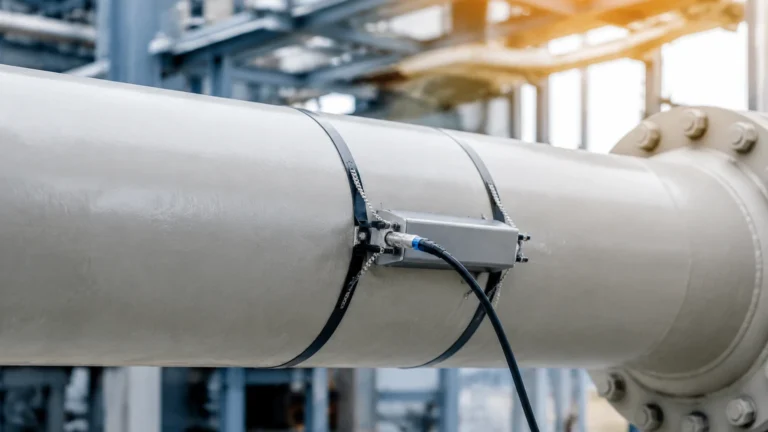
* Coriolis vs. Ultrasonic: Ultrasonic meters are excellent for large pipes and non-intrusive measurement but are sensitive to flow profiles and fluid density changes. Coriolis provides higher absolute accuracy for smaller line sizes.
* Coriolis vs. Vortex: Vortex meters are cost-effective for steam and gas but have a limited turndown ratio and cannot measure mass directly without external pressure and temperature compensation.
Frequently Asked Questions
Q: Can a Coriolis meter measure steam?
A: Yes, but it is generally limited to saturated or superheated steam where the mass flow rate is high enough to generate a detectable phase shift. For very low-pressure steam, vortex meters are often more economical.
Q: Does the viscosity of the fluid affect the accuracy?
A: No. One of the primary strengths of the Coriolis principle is that it is independent of viscosity and Reynolds number. It is highly effective for everything from water to thick polymers and resins.
Q: How often does a Coriolis meter need calibration?
A: Because there are no moving parts subject to wear (the tubes only vibrate slightly), Coriolis meters are extremely stable. In many non-corrosive applications, they can operate for several years without needing recalibration, though regular "zero-point" checks are recommended.
Q: Is it possible to use a Coriolis meter for bidirectional flow?
A: Yes. The phase shift will simply reverse its sign depending on the direction of the flow, allowing the meter to accurately track both forward and reverse totals.
Conclusion
The Coriolis mass flow meter represents the pinnacle of flow measurement technology for many industrial sectors. By leveraging the fundamental laws of physics, it provides a direct, highly accurate measurement of mass, density, and temperature in a single device. While the initial investment is higher than some alternatives, the reduction in measurement error, lower maintenance requirements, and elimination of secondary sensors often result in a lower total cost of ownership.
For professionals in water treatment, chemical processing, and industrial automation, selecting the right instrument involves balancing technical requirements with budget constraints. For a comprehensive look at how these instruments integrate with level measurement and other process controls, visit the Main Page for technical documentation and expert support.