In Line Gas Analyzer
In Line Gas Analyzer
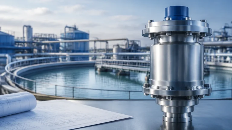
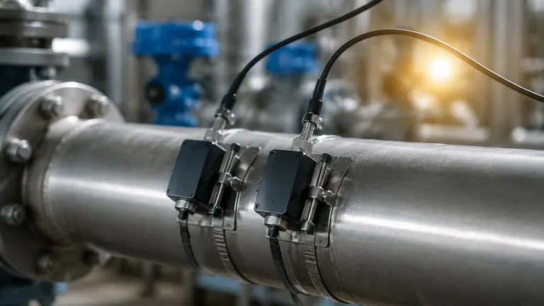
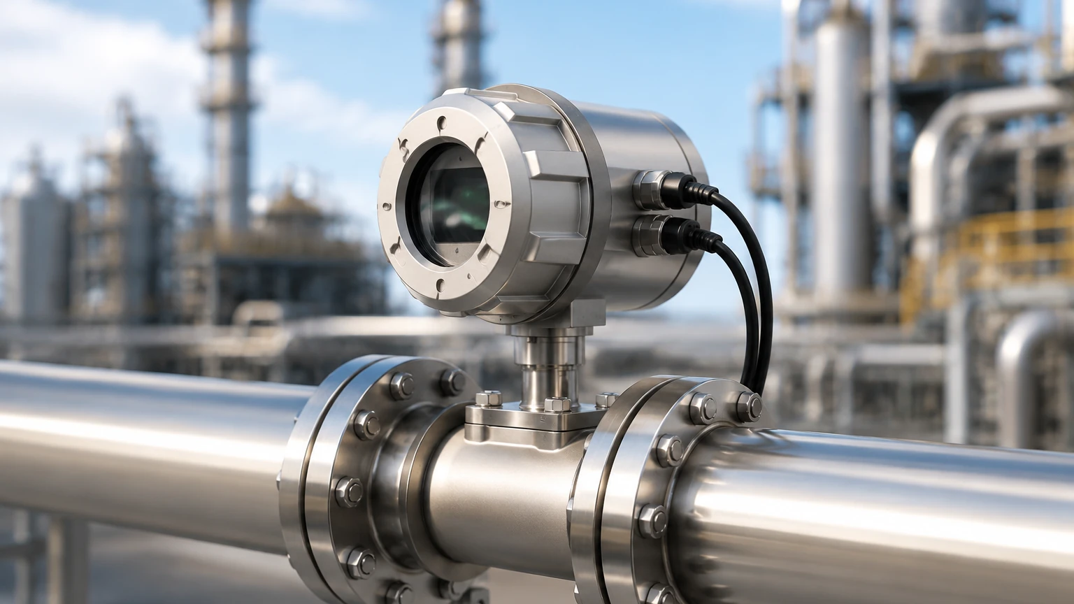
In the landscape of industrial process control, the ability to monitor gas concentrations in real-time is fundamental to safety, efficiency, and environmental compliance. An in line gas analyzer refers to an instrument installed directly into a process pipe or vessel, providing continuous measurement without the need for complex sampling systems. This technology contrasts with extractive analysis, where gas is pulled from the process, conditioned, and sent to a remote analyzer. For engineers managing complex chemical, oil and gas, or water treatment facilities, understanding the mechanics and selection criteria of in-line analysis is as critical as mastering level measurement technologies.
While Welk specializes in industrial level measurement—such as radar and ultrasonic sensors—the integration of gas analysis often occurs in the same process environments. For instance, monitoring the headspace gas in a storage tank is a common requirement alongside tracking the liquid level. For a comprehensive overview of industrial instrumentation and to explore how these systems integrate into broader automation frameworks, engineers often refer to the Main Page of leading equipment providers.
Measurement Principles of In Line Gas Analyzers
Before selecting an analyzer, it is essential to understand the physics behind the measurement. In-line systems typically utilize optical or electrochemical principles to identify and quantify specific gas molecules.
Tunable Diode Laser Absorption Spectroscopy (TDLAS)
TDLAS is widely considered the gold standard for in-line analysis in harsh environments. It operates on the principle of light absorption. A laser diode emits light at a specific wavelength corresponding to the absorption line of the target gas (e.g., Ammonia, Moisture, or Carbon Monoxide). As the laser beam passes through the gas stream, the molecules absorb a portion of the light. The detector on the opposite side measures the attenuation, which is proportional to the gas concentration according to the Beer-Lambert Law.
Because the laser is "tunable," it can scan across a very narrow wavelength range, effectively ignoring interference from other gases. This makes it highly selective and ideal for "cross-stack" installations where the gas may contain dust or moisture.
Non-Dispersive Infrared (NDIR)
NDIR analyzers use an infrared (IR) lamp as a light source. The light passes through a filter that only allows specific IR wavelengths to pass. When the target gas (such as CO2 or Methane) is present, it absorbs the IR light. A detector measures the remaining intensity. While less selective than TDLAS, NDIR is a cost-effective solution for many common industrial gases. However, in-line NDIR often requires a specialized probe or a bypass loop to ensure the optical path remains clean.
Zirconia Oxygen Sensing
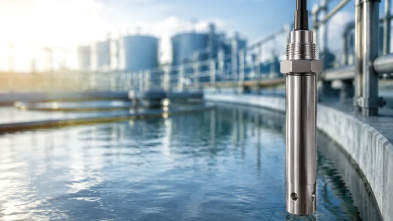
For high-temperature applications, such as combustion control in boilers, Zirconia (ZrO2) sensors are used for in-line oxygen measurement. At temperatures above 600°C (1112°F), the zirconia ceramic becomes an oxygen ion conductor. By maintaining a reference gas (usually ambient air) on one side of the ceramic and the process gas on the other, a voltage is generated proportional to the difference in oxygen partial pressure.
Electrochemical Sensors
Electrochemical sensors involve a chemical reaction between the target gas and an electrode. These are commonly used for toxic gas detection (H2S, Cl2) or oxygen monitoring in ambient or low-pressure environments. While compact and relatively inexpensive, they are "consumable" and require periodic replacement as the electrolyte or electrodes degrade over time.
Practical Selection Table for Gas Analysis
Choosing the right in line gas analyzer depends on the chemical composition of the stream, the temperature, and the required response time.
| Technology | Common Target Gases | Typical Accuracy | Operating Temperature | Maintenance Level |
| :— | :— | :— | :— | :— |
| TDLAS | NH3, H2O, CO, O2, HCl | ±1% of Reading | Up to 600°C (1112°F) | Low (No contact) |
| NDIR | CO2, CH4, CO, SO2 | ±2% Full Scale | Up to 150°C (302°F) | Moderate (Optical cleaning) |
| Zirconia | O2 (Oxygen) | ±1% of Reading | 600°C to 1400°C | High (Heating element) |
| Electrochemical| O2, H2S, CO, NO2 | ±2-5% Full Scale | -20°C to 50°C | High (Sensor replacement) |
Installation Considerations for In-Line Systems
The performance of an in line gas analyzer is heavily influenced by its physical installation. Unlike level meters, which are often top-mounted on tanks, gas analyzers must account for flow dynamics and potential contaminants.
1. Probe Location and Flow Profile
To achieve a representative sample, the analyzer probe should be installed in a section of the pipe where the gas is well-mixed. Engineers should avoid installing sensors immediately after a bend or a valve. A general rule of thumb is to allow for 5 to 10 pipe diameters of straight run upstream and 3 to 5 diameters downstream. If the gas velocity is extremely high (e.g., >20 m/s), a protective shroud may be necessary to prevent erosion of the sensor tip.
2. Temperature and Pressure Compensation
Gas density changes with temperature and pressure, which directly affects the concentration measurement. Most modern in line gas analyzers include integrated temperature and pressure sensors to provide "compensated" readings (Standardizing the output to 0°C and 101.325 kPa). If the process conditions fluctuate wildly, an external high-precision pressure transmitter may be required to feed data into the analyzer’s CPU.
3. Flange Alignment and Optical Path
For cross-stack TDLAS systems, the transmitter and receiver units must be perfectly aligned across the diameter of the pipe or stack. Even a slight misalignment due to pipe vibration or thermal expansion can lead to signal loss. Using heavy-duty mounting flanges (e.g., DN50 or 2" ANSI) and thermal isolators is recommended in high-temperature applications.
4. Purging Systems
In processes containing high levels of dust, soot, or corrosive vapors, a purge system is vital. Clean, dry instrument air or Nitrogen is injected into the sensor housing to create a "curtain" that prevents process gas from fouling the optical windows. The purge flow must be regulated to ensure it does not dilute the gas being measured at the sensor tip.
Limitations and Common Risks
Despite their advantages, in-line analyzers face specific challenges that can lead to measurement drift or hardware failure.
* Condensation: If the process gas cools below its dew point, liquid droplets can form on the sensor or optical windows. This is particularly problematic in flue gas analysis. Heated probes and insulated enclosures are the primary defenses against condensation.
* Cross-Sensitivity: In complex chemical mixtures, one gas may absorb light at a wavelength very close to the target gas. For example, high concentrations of CO2 can sometimes interfere with certain NDIR-based methane measurements. TDLAS minimizes this risk but does not eliminate it entirely in high-pressure environments where spectral lines broaden.
* Calibration Drift: All sensors experience some degree of drift. While in-line systems are designed for long-term stability, they still require periodic validation. Many engineers use a "validation port" near the analyzer to inject a known span gas to check accuracy without removing the instrument from the line.
Integration with Level Measurement Systems
In many B2B industrial scenarios, gas analysis and level measurement are two sides of the same coin. For example, in Nitrogen blanketing systems for chemical storage tanks, a radar level meter (such as those found on the Main Page) tracks the liquid volume, while an in-line oxygen analyzer monitors the headspace. If the oxygen level rises, it indicates a breach in the blanket, posing a fire or oxidation risk. Integrating these two data points into a single PLC (Programmable Logic Controller) allows for automated safety shutdowns and efficient gas usage.
Frequently Asked Questions (FAQ)
Q: How often does an in line gas analyzer need calibration?
A: This depends on the technology. TDLAS systems are often stable for 6 to 12 months. Electrochemical sensors may require monthly checks. Always refer to the manufacturer’s specific drift specifications.
Q: Can in-line analyzers be used in hazardous areas?
A: Yes, most industrial gas analyzers are available with ATEX, IECEx, or Class I Div 1 certifications. These versions use explosion-proof housings or intrinsic safety barriers.
Q: What is the maximum pipe diameter for a cross-stack analyzer?
A: For TDLAS, paths can range from 0.5 meters to over 15 meters. However, as the distance increases, the laser beam diverges, and the signal-to-noise ratio decreases, requiring higher-powered lasers or more sensitive detectors.
Q: How does dust affect the measurement?
A: In optical systems, dust scatters light. While TDLAS can handle significant "transmission loss" (often up to 90% light blockage), extreme dust levels will eventually cause a signal-low alarm. Effective purging is the best solution.
Conclusion
Implementing an in line gas analyzer is a strategic move for facilities looking to transition from reactive sampling to proactive process control. By understanding the underlying principles—whether it be the precision of TDLAS or the robustness of Zirconia—and adhering to strict installation guidelines, engineers can ensure reliable data for years. When combined with accurate level measurement and other process instrumentation, these analyzers form the backbone of a safe and optimized industrial operation.