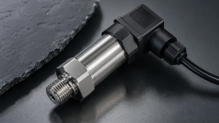
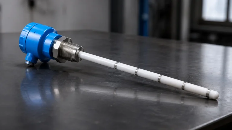
Inline Conductivity Meter
Inline Conductivity Meter
In industrial process control, the ability to monitor fluid properties in real-time is essential for maintaining product quality, ensuring equipment longevity, and optimizing chemical usage. An inline conductivity meter is a critical analytical instrument used to measure the ability of a solution to conduct an electrical current. This measurement is directly proportional to the concentration of dissolved ions in the liquid, making it an invaluable proxy for monitoring salinity, dissolved solids, and chemical concentrations in water treatment, food and beverage, and chemical processing industries.
While many facilities focus heavily on physical parameters such as pressure or volume—often utilizing specialized tools found on the Main Page of instrumentation catalogs—the chemical composition monitored by conductivity sensors provides a deeper look into the process health itself. This guide provides a comprehensive technical overview of inline conductivity measurement, including principles, sensor types, selection criteria, and installation best practices.
Understanding Conductivity Measurement Principles
Conductivity is the reciprocal of electrical resistivity. In a liquid, current is carried by cations (positively charged ions) and anions (negatively charged ions). The measurement is typically expressed in Siemens per meter (S/m), though in industrial applications, it is more commonly reported in microsiemens per centimeter (µS/cm) or millisiemens per centimeter (mS/cm).
The Role of the Cell Constant (K)
An inline conductivity meter determines conductivity by measuring the conductance (G) between two or more electrodes. The relationship between conductance and conductivity (κ) is defined by the cell constant (K):
κ = G × K
The cell constant is determined by the geometry of the sensor: K = L / A, where L is the distance between the electrodes and A is the surface area of the electrodes.
* Low Cell Constants (K=0.01 to 0.1 cm⁻¹): Used for high-purity water where the distance between electrodes is small or the surface area is large.
* Standard Cell Constants (K=1.0 cm⁻¹): Used for general-purpose water and wastewater applications.
* High Cell Constants (K=10 cm⁻¹): Used for highly conductive liquids like concentrated acids or brines.
Temperature Compensation
Conductivity is highly temperature-dependent. As the temperature of a solution increases, the viscosity typically decreases, allowing ions to move more freely, which increases conductivity. For most aqueous solutions, conductivity increases by approximately 2% per degree Celsius. To provide standardized readings, an inline conductivity meter must include an integrated temperature sensor (usually a Pt100 or Pt1000 RTD) to perform automatic temperature compensation (ATC), usually referencing the value to a standard 25°C (77°F).
Types of Inline Conductivity Sensors
There are two primary technologies used for inline conductivity measurement: contacting and inductive (toroidal). Choosing the correct technology depends on the expected conductivity range and the chemical nature of the process fluid.
1. Contacting Conductivity Sensors
In a contacting sensor, the electrodes come into direct physical contact with the process fluid. These are categorized by the number of poles used:
* Two-Pole Sensors: The simplest design, using two electrodes to apply a voltage and measure the resulting current. While cost-effective, they are susceptible to "polarization," where ions build up near the electrode surface, creating a resistance that skews the reading. They are best suited for low-conductivity applications like pure water.
* Four-Pole Sensors: These use four electrodes. Two electrodes apply a current, and two separate electrodes measure the voltage drop. This design eliminates the effects of polarization and electrode fouling (to a certain extent), allowing for a much wider measurement range.
2. Inductive (Toroidal) Conductivity Sensors
Inductive sensors, often called toroidal sensors, do not have electrodes that touch the liquid. Instead, they use two wire-wound coils (toroïds) encased in a non-conductive plastic housing (such as PEEK, PFA, or Polypropylene). One coil acts as a transmitter, inducing an alternating current in the surrounding conductive liquid. The second coil acts as a receiver, measuring the magnitude of this current, which is proportional to the conductivity.
Inductive sensors are ideal for high-conductivity liquids, highly corrosive chemicals, or fluids with high suspended solids that would quickly foul or corrode traditional metal electrodes.
Key Selection Criteria for Industrial Applications
Selecting the right inline conductivity meter requires an analysis of the process environment. Engineers should consult the following table for a baseline comparison:
| Feature | Contacting (2-Pole/4-Pole) | Inductive (Toroidal) |
| :— | :— | :— |
| Measurement Range | 0.01 µS/cm to 200 mS/cm | 100 µS/cm to 2,000 mS/cm |
| Best Use Case | Pure water, RO systems, Boiler feed | Acids, bases, brines, wastewater |
| Fouling Resistance | Low (Susceptible to scaling) | High (Non-contacting) |
| Maintenance | Frequent cleaning/calibration | Minimal maintenance |
| Material Options | Stainless Steel, Graphite, Titanium | PEEK, PFA, Polypropylene |
| Installation Size | Compact | Larger sensor diameter |
Material Compatibility
For contacting sensors, 316L Stainless Steel is the industry standard, but for aggressive chemicals, Titanium or Monel may be required. For inductive sensors, the outer jacket material must be checked against the chemical compatibility of the process fluid. PEEK is widely used for its mechanical strength and chemical resistance at high temperatures, whereas PFA is preferred for extremely aggressive acids.
Pressure and Temperature Ratings
Inline sensors are subject to the full force of the process flow. Standard industrial sensors are typically rated for pressures up to 10-16 bar (145-232 psi) and temperatures up to 130°C (266°F). In high-temperature applications, such as steam condensate monitoring, specialized high-temp electrode materials and cooling jackets for the electronics may be necessary.
Installation and Engineering Best Practices
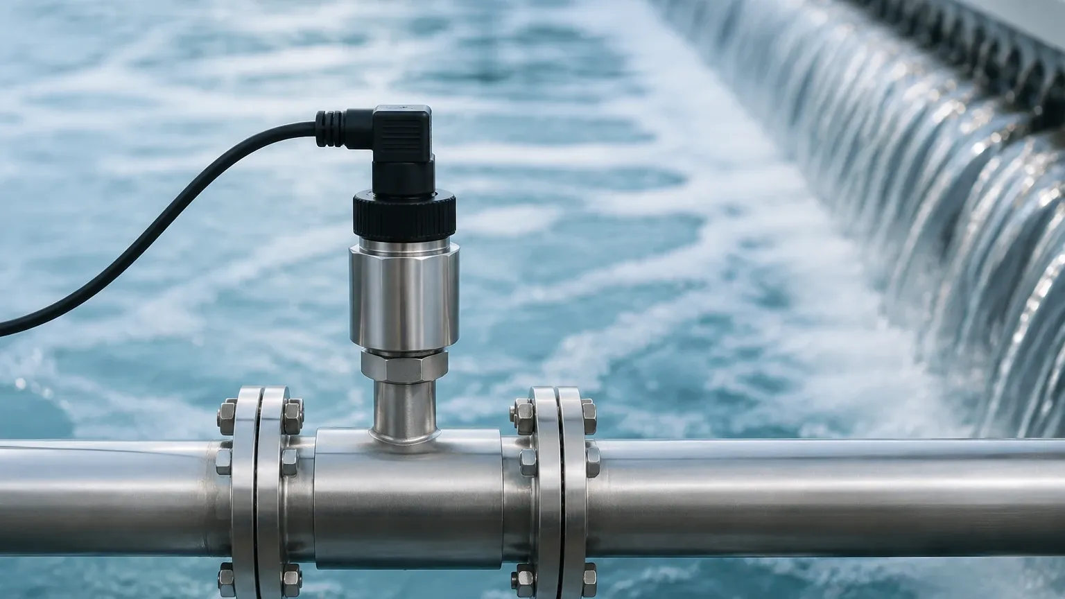
Proper installation is paramount to achieving accurate and repeatable measurements. An inline conductivity meter that is poorly positioned will suffer from signal noise, air entrapment, or excessive fouling.
1. Sensor Orientation and Location
* Full Pipe Requirement: The sensor must be installed in a location where the pipe is always completely full of liquid. If air pockets or bubbles form around the electrodes, the meter will read significantly lower than the actual conductivity.
* Upward Flow: In vertical pipe runs, the flow should be directed upwards to ensure the pipe remains full and to help sweep away any air bubbles.
* Avoid Dead Zones: Do not install sensors in stagnant sections of piping or at the very bottom of a horizontal pipe where sediment can accumulate.
2. Insertion Depth
For contacting sensors, the electrodes must be fully submerged in the flow stream. However, they should not be placed so deep that they obstruct the flow or become damaged by high-velocity debris. For inductive sensors, a minimum clearance (usually 2-3 cm) is required between the sensor head and the pipe wall to prevent the wall from interfering with the magnetic field.
3. Interference and Grounding
Conductivity measurements involve low-level electrical signals that are susceptible to electromagnetic interference (EMI).
* Use shielded cabling for all sensor connections.
* Ensure the process piping is properly grounded, especially when using plastic piping systems. In non-conductive pipes, grounding rings may be required to provide a stable electrical reference.
Limitations and Maintenance Requirements
While modern inline conductivity meters are robust, they are not "set and forget" instruments. Understanding their limitations is key to long-term reliability.
Common Risks and Limitations
1. Polarization: As mentioned, this affects 2-pole contacting sensors in high-conductivity solutions. It results in a non-linear response and underestimated values.
2. Fouling and Scaling: In water with high hardness, calcium carbonate can scale onto the electrodes, effectively increasing the cell constant and lowering the measured conductivity. Regular cleaning with a mild acid solution is often required.
3. Air Bubbles: Air is a perfect insulator. Even small micro-bubbles clinging to the electrode surface will drastically reduce the measured conductance.
Calibration Procedures
Calibration should be performed using certified conductivity standards that bracket the expected process range. For example, if the process typically runs at 1,413 µS/cm, a calibration standard of 1,413 µS/cm should be used.
* Wet Calibration: The sensor is removed from the line, cleaned, and placed in a standard solution.
* Comparison Calibration: A portable, calibrated conductivity meter is used to measure a grab sample taken from the process line, and the inline meter is adjusted to match. This is less accurate due to potential temperature and CO2 absorption changes in the grab sample.
Frequently Asked Questions (FAQ)
Q: Can I use a contacting sensor for seawater measurement?
A: While possible with a 4-pole sensor, an inductive (toroidal) sensor is generally preferred for seawater (approx. 50 mS/cm) because it resists the corrosive nature of the salt and is not affected by the high ion concentration that causes polarization in 2-pole sensors.
Q: How often should an inline conductivity meter be calibrated?
A: This depends on the application. In high-purity water, calibration may only be needed annually. In wastewater or chemical blending, monthly or even weekly checks may be necessary due to sensor fouling.
Q: What is the difference between Conductivity and TDS?
A: Total Dissolved Solids (TDS) is a measure of the mass of dissolved material. Conductivity meters often estimate TDS by multiplying the conductivity value by a factor (typically between 0.5 and 0.7). However, this factor varies depending on the specific ions present in the water.
Conclusion
The inline conductivity meter is a versatile and essential tool for modern industrial automation. By understanding the physical principles of ion movement and the technical differences between contacting and inductive sensing, engineers can select the most appropriate instrument for their specific chemical environment. Whether managing pure water for pharmaceutical use or monitoring high-strength acids in chemical manufacturing, proper selection and installation ensure that these meters provide the accurate data necessary for process optimization.
For engineers looking to integrate conductivity monitoring with other process variables like liquid level or flow, exploring comprehensive instrument suites—such as those detailed on the Welk Main Page—provides a roadmap for building a fully automated and reliable measurement system. Proper maintenance and a clear understanding of the cell constant and temperature effects remain the foundation of any successful analytical measurement strategy.