Io-link Magmeter
Io-link Magmeter
In the landscape of industrial automation, the demand for data-driven decision-making has transformed traditional instrumentation. The electromagnetic flowmeter, or magmeter, has long been a staple for measuring the flow of conductive liquids. However, the integration of IO-Link technology has elevated these devices from simple sensors to intelligent components within a Smart Factory framework. An IO-Link magmeter provides not only precise flow rates but also a wealth of diagnostic and process data that traditional 4-20mA analog signals cannot transmit. This guide explores the principles, advantages, and selection criteria for implementing IO-Link magmeters in modern process environments.
Measurement Principles of Electromagnetic Flowmeters
Before delving into the digital communication aspects, it is essential to understand the underlying physics of the device. All magmeters operate based on Faraday’s Law of Electromagnetic Induction. This principle states that a voltage is induced when a conductive medium moves through a magnetic field.
Faraday’s Law in Practice
The mathematical representation of this principle is $E = B \cdot v \cdot d$, where:
- E is the induced voltage (the signal).
- B is the strength of the magnetic field generated by the meter’s coils.
- v is the velocity of the conductive liquid.
- d is the distance between the electrodes (typically the inner diameter of the pipe).
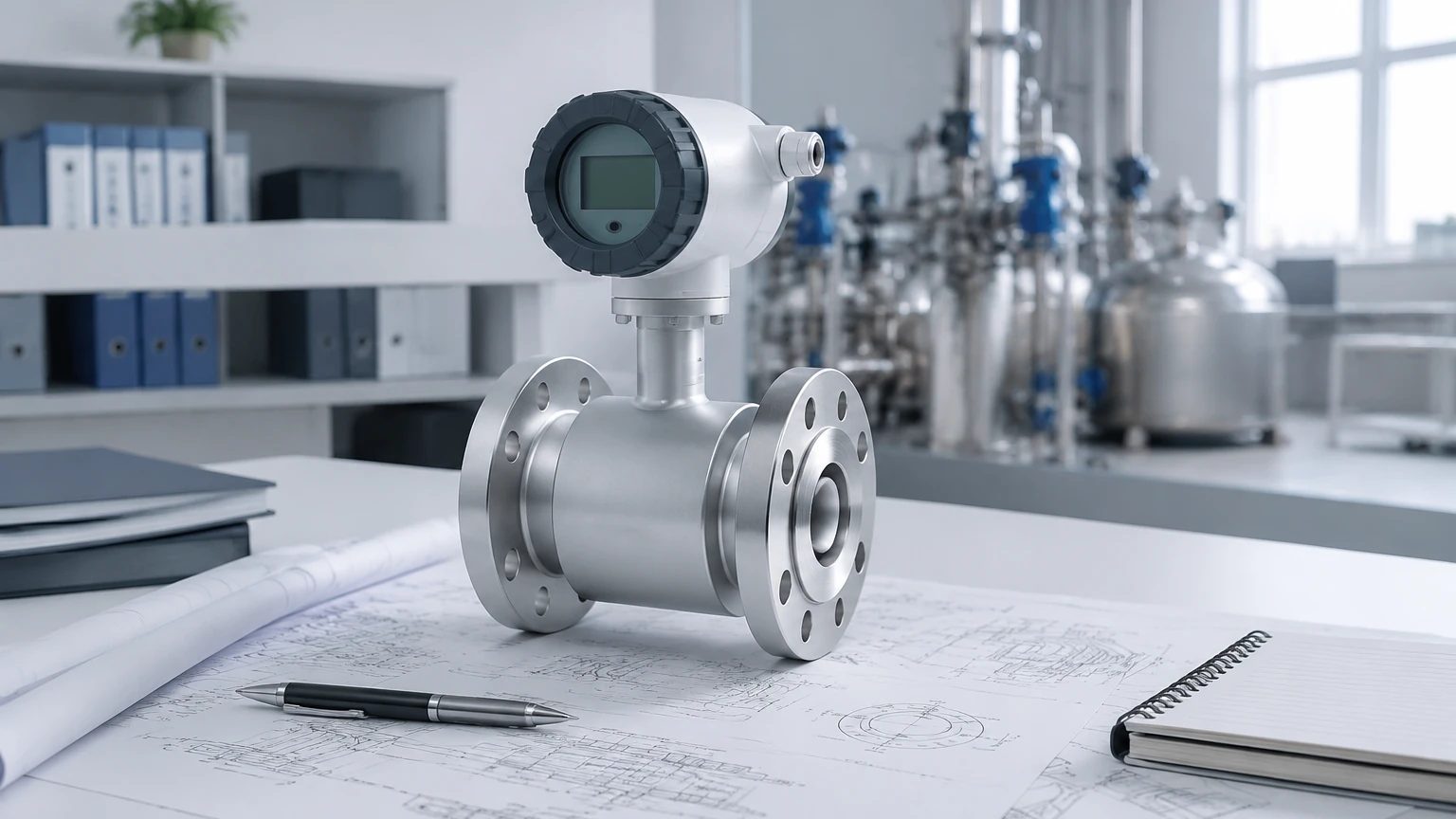
In an IO-Link magmeter, the sensor body contains electromagnetic coils that create a magnetic field perpendicular to the flow direction. As a conductive liquid—such as water, acids, or slurries—passes through this field, it generates a voltage. Two electrodes, mounted flush with the pipe wall, pick up this microvolt-level signal. The internal electronics then process this signal to calculate the volumetric flow rate. Because the induced voltage is directly proportional to the flow velocity, the measurement is inherently linear.
Conductivity Requirements
A critical limitation of the magmeter principle is that the fluid must be electrically conductive. Most industrial magmeters require a minimum conductivity of 5 μS/cm (microsiemens per centimeter). Consequently, these meters are unsuitable for hydrocarbons, deionized water, or gases, which lack the necessary ions to induce a measurable voltage.
Understanding the IO-Link Integration
IO-Link (IEC 61131-9) is the first worldwide standardized IO technology for communication with sensors and actuators. It is a point-to-point, short-distance (up to 20 meters), digital communication protocol that sits above the fieldbus level. When a magmeter is equipped with IO-Link, it changes how the device interacts with the Control Level (PLC).
Beyond the Analog Signal
Traditional magmeters typically output a 4-20mA signal representing the flow rate. While reliable, this analog signal is susceptible to electromagnetic interference (EMI) and requires manual scaling in the PLC. An IO-Link magmeter transmits data digitally, eliminating conversion errors and providing three distinct types of data:
1. Process Data: Real-time information including flow velocity, totalized volume, and often the temperature of the medium.
2. Service Data (Parameter Data): Information about the device itself, such as model numbers, serial numbers, and configuration settings that can be read or written remotely.
3. Event Data: Notifications regarding device status, such as "Empty Pipe" detection, electrode fouling, or internal hardware errors.
By utilizing these data streams, engineers can Review product options and application support to ensure their systems are optimized for both performance and maintenance.
Key Evaluation Criteria for Selection
Selecting the right IO-Link magmeter requires a balance between process requirements and communication needs. Engineers should evaluate the following factors to ensure long-term reliability.
Liner and Electrode Materials
The internal liner protects the meter body from the process fluid and ensures the magnetic field is not short-circuited by a metal pipe. Common materials include:
- PTFE/PFA: Excellent chemical resistance for aggressive acids and high temperatures.
- EPDM/Hard Rubber: Suitable for water treatment and mildly abrasive slurries.
- Ceramic: Ideal for highly abrasive or extremely high-temperature applications.
Electrodes must also be compatible with the fluid. While Stainless Steel 316L is standard, Hastelloy C, Tantalum, or Platinum may be required for specific chemical resistances.
Accuracy and Turndown Ratio
Most industrial-grade magmeters offer an accuracy of ±0.5% of the measured value, though high-precision models can reach ±0.2%. The turndown ratio—the range over which the meter maintains its accuracy—is typically 100:1 or better, making magmeters excellent for processes with widely varying flow rates.
Selection Table: Standard vs. IO-Link Magmeter
| Feature | Standard Magmeter (Analog) | IO-Link Magmeter (Digital) |
| :— | :— | :— |
| Data Transmission | Analog (4-20mA / Pulse) | Digital (Bi-directional) |
| Wiring | Shielded multi-core cable | Unshielded 3-wire M12 cable |
| Diagnostics | Basic (via local display) | Advanced (Remote via PLC/HMI) |
| Configuration | Manual (Buttons/HART) | Remote (IODD file upload) |
| Process Values | Single (Flow only) | Multiple (Flow, Temp, Totalizer) |
| Signal Integrity | Prone to EMI/RFI | Immune to analog noise |
Installation Considerations
To achieve the specified accuracy, the physical installation of an IO-Link magmeter must follow strict engineering guidelines. Even the most advanced digital sensor will provide inaccurate data if the hydraulic conditions are poor.
Straight Pipe Runs
Flow profiles must be fully developed and stable as they pass through the meter. Turbulence caused by valves, pumps, or elbows can lead to measurement errors. The standard recommendation is to have a straight pipe run of at least 5 diameters (5D) upstream of the meter and 2 diameters (2D) downstream. If space is limited, some specialized "zero-run" meters use multiple electrodes to compensate for distorted flow profiles, though these are less common in standard IO-Link configurations.
Grounding and Potential Equalization
Since the induced voltage is extremely small, any stray electrical currents in the piping can interfere with the signal. Proper grounding is mandatory. If the meter is installed in a plastic or lined pipe, grounding rings must be used on both sides of the meter to ensure the fluid is at the same electrical potential as the meter body.
Orientation and Filling
The meter must always be completely full of liquid. For this reason, vertical installation with upward flow is preferred. In horizontal installations, the electrode axis must be horizontal (not vertical) to prevent air bubbles at the top or sediment at the bottom from interfering with the electrode contact.
Common Risks and Limitations
While IO-Link magmeters are versatile, they are not a universal solution. Engineers must be aware of the following risks:
* Conductivity Fluctuations: If a process involves mixing fluids, the conductivity must remain above the meter's threshold. If the liquid becomes non-conductive, the meter will report a zero flow or an error.
* Vacuum Conditions: Some liners, particularly PTFE, can collapse or be pulled away from the meter body if the pipe experiences a vacuum. PFA liners with stainless steel mesh reinforcement are usually required for vacuum applications.
* Coating and Fouling: In wastewater or slurry applications, fats, oils, or minerals can build up on the electrodes. While IO-Link can provide a diagnostic warning for this, periodic cleaning or the use of ultrasonic electrode cleaning may be necessary.
* Ambient Temperature: The electronics in IO-Link devices are often compact. In high-temperature processes, it is vital to ensure that the ambient temperature around the transmitter does not exceed its rating (typically 60°C).
Frequently Asked Questions (FAQ)
Q: Can I use an IO-Link magmeter with a standard 4-20mA PLC input?
A: No directly. IO-Link is a digital protocol. You would need an IO-Link Master to convert the signal to a fieldbus (like PROFINET or EtherNet/IP) or use a meter that offers both IO-Link and a secondary analog output.
Q: What is an IODD file?
A: The IODD (IO Device Description) is a digital file that contains all the parameters and properties of the sensor. It allows the PLC or configuration software to recognize the device and display its data correctly without manual programming.
Q: How does IO-Link improve maintenance?
A: It enables "Device Replacement Without Tools." When a sensor is replaced, the IO-Link Master can automatically push the previous configuration settings to the new sensor, minimizing downtime and eliminating setup errors.
Q: Does the cable length affect accuracy?
A: Unlike analog signals, where long cable runs can lead to voltage drops or noise interference, IO-Link is digital. As long as you stay within the 20-meter limit, the data remains 100% accurate. For longer distances, an IO-Link Master can be placed closer to the sensor and connected to the PLC via Ethernet.
Conclusion and Next Steps
The transition to an IO-Link magmeter represents a significant step forward in process transparency. By providing high-resolution flow data alongside temperature and diagnostic status, these devices reduce the total cost of ownership through simplified wiring and proactive maintenance. When evaluating your next installation, ensure that the fluid conductivity, liner compatibility, and hydraulic conditions align with the technical specifications of the meter. For those seeking comprehensive solutions in level and flow measurement, visiting the Main Page provides access to a wider range of industrial instrumentation designed for demanding environments.