Ko Drum
Ko Drum
In the landscape of industrial process engineering, the knock-out drum, commonly referred to as a ko drum, serves as a critical safety and operational component. Primarily designed to separate liquid droplets from a gas or vapor stream, these vessels protect downstream equipment such as compressors, turbines, and flare systems from the damaging effects of liquid carryover. Whether it is a flare knock-out drum in a refinery or a suction scrubber in a natural gas compression station, the fundamental goal remains the same: ensuring that the gas phase is sufficiently dry for its intended application.
Effective management of a ko drum relies heavily on accurate level measurement. Without reliable data on the accumulated liquid, the risk of "slugging"—where a large volume of liquid enters the gas outlet—increases, potentially leading to catastrophic mechanical failure or environmental non-compliance. This guide explores the engineering principles of ko drums, the technologies used to monitor them, and the selection criteria for industrial level instrumentation.
Fundamental Principles of Liquid-Gas Separation
The operation of a ko drum is governed by the principles of fluid mechanics, specifically the separation of phases through gravity, impingement, and centrifugal force. Understanding these principles is essential before selecting the appropriate level measurement technology.
Gravity Separation
Gravity is the primary mechanism in most ko drums. As a gas stream enters the larger volume of the drum, its velocity decreases significantly. According to Stokes' Law, if the upward velocity of the gas is lower than the settling velocity of the liquid droplets, the droplets will fall to the bottom of the vessel. The design must account for the minimum droplet size (typically 150 to 600 microns in standard gravity separators) that needs to be removed.
Impingement and Coalescence
To improve efficiency and remove smaller droplets (down to 10 microns), many ko drums incorporate internal components such as mist eliminators or vane packs. When the gas stream passes through these structures, liquid droplets impinge on the surfaces, coalesce into larger drops, and eventually fall to the liquid collection section due to gravity.
Centrifugal Force
In some specialized vertical ko drums, the inlet is designed tangentially to create a cyclone effect. The centrifugal force flings the heavier liquid droplets against the vessel walls, where they drain downward, while the lighter gas exits through the center.
The Critical Role of Level Measurement in KO Drums
Level measurement in a ko drum is not merely for inventory tracking; it is a vital safety function. There are three primary reasons why precise level monitoring is mandatory:
1. Preventing Carryover: If the liquid level rises too high, the residence time for gas decreases, increasing gas velocity and allowing liquid to be swept into the outlet. In flare systems, this can result in "burning rain," where flaming liquid is ejected from the flare tip.
2. Pump Control: Most ko drums are equipped with automated pump-out systems. Level sensors trigger the start and stop of these pumps to maintain the level within a safe operating window.
3. Equipment Protection: For compressor suction ko drums, even small amounts of liquid can cause "liquid slugging," which destroys compressor valves and pistons. High-high level switches are often interlocked to shut down the entire process to prevent such damage.
For engineers seeking comprehensive solutions for these applications, the Main Page of Welk provides a technical overview of the instruments capable of handling these demanding environments.
Level Measurement Technologies for KO Drum Applications
Selecting the right instrument requires an understanding of the physical properties of the liquid (e.g., hydrocarbons, water, or chemicals) and the operating conditions (pressure and temperature).
Guided Wave Radar (GWR)
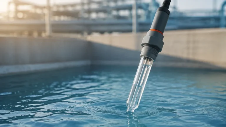
Guided Wave Radar is widely considered the gold standard for ko drum level measurement. It operates on the principle of Time Domain Reflectometry (TDR). A low-energy electromagnetic pulse is sent down a probe (waveguide). When the pulse hits the liquid surface, a portion of the energy is reflected back to the transmitter. The time taken is proportional to the distance.
* Advantages: GWR is unaffected by changes in pressure, temperature, or gas phase composition. It performs exceptionally well even if the liquid has a low dielectric constant, which is common in hydrocarbon ko drums.
* Limitations: The probe is in contact with the process, which may require specific material compatibility (e.g., 316 Stainless Steel or Hastelloy).
Non-Contact Radar
Non-contact radar transmitters, particularly those operating at 80 GHz, offer a high-frequency solution that does not touch the medium. They emit a signal that reflects off the liquid surface.
* Advantages: No moving parts and no contact with the fluid make it ideal for corrosive or dirty liquids. Modern 80 GHz units have a very narrow beam angle, allowing them to be installed in vessels with internal obstructions like mist eliminators.
* Limitations: High-pressure steam or heavy foam can sometimes attenuate the signal, though advanced signal processing has mitigated much of this risk.
Ultrasonic Level Sensors
Ultrasonic sensors use sound waves to measure the distance to the liquid surface. While cost-effective, they are generally limited to atmospheric or low-pressure ko drums.
* Principle: The sensor emits an ultrasonic pulse that reflects off the liquid. The travel time is converted to distance.
* Limitations: Sound speed varies with air temperature and gas composition. Furthermore, ultrasonic waves cannot travel through a vacuum and are easily absorbed by foam.
Magnetic Level Gauges (MLG)
For high-pressure applications where visual confirmation is required, Magnetic Level Gauges are often used. They consist of a bypass chamber mounted to the side of the ko drum. A float containing a magnet moves with the liquid level, flipping colored flags on an external scale.
* Advantages: Provides a clear visual indication without requiring power. Can be fitted with reed switches or transmitters for remote monitoring.
* Limitations: Not suitable for extremely viscous liquids that might cause the float to stick.
Selection Criteria and Technical Comparison
When specifying instrumentation for a ko drum, engineers must evaluate the following parameters:
| Feature | Guided Wave Radar | Non-Contact Radar (80GHz) | Ultrasonic | Magnetic Level Gauge |
| :— | :— | :— | :— | :— |
| Accuracy | ±2 mm | ±1 mm | ±0.25% of range | ±5 mm |
| Pressure Range | Up to 40 MPa | Up to 16 MPa | Atmospheric | Up to 25 MPa |
| Temp. Range | -196°C to 450°C | -40°C to 200°C | -40°C to 80°C | -196°C to 400°C |
| Foam Resistance | Excellent | Good | Poor | Excellent |
| Maintenance | Low | Very Low | Moderate | Moderate |
Installation Considerations and Best Practices
The physical installation of a level sensor on a ko drum is as important as the technology itself. Poor placement can lead to false readings and system failures.
1. Nozzle Location: The level sensor should be installed away from the inlet nozzle. The turbulence and splashing caused by the incoming gas/liquid stream can create "noise" in the measurement signal.
2. Stilling Wells and Bypass Chambers: For GWR or non-contact radar in highly turbulent drums, a stilling well (a pipe inside the vessel) or an external bypass chamber is recommended. This provides a calm liquid surface for accurate measurement.
3. Venting: If using a bypass chamber, ensure it is properly vented back to the vapor space of the ko drum to ensure the levels in the chamber and the vessel are equal.
4. Dead Zones: Every radar and ultrasonic sensor has a "dead zone" or "blocking distance" near the top of the sensor where measurement is not possible. Ensure the nozzle height accounts for this to prevent missing a high-level condition.
Limitations and Operational Challenges
Despite advancements in technology, certain conditions in a ko drum remain challenging:
* Foaming: In amine or glycol ko drums, foam can build up on the liquid surface. Foam is a poor reflector for radar and a high absorber for ultrasonic waves. GWR is generally the best choice here as it can often "see through" light foam to the true liquid level.
* Interface Measurement: In some ko drums, both water and hydrocarbons are collected. If the goal is to drain only the water, an interface measurement is required. GWR is uniquely capable of measuring both the upper liquid level and the interface level between two liquids of different dielectrics.
* Condensation: High-humidity gas streams can cause condensation on the sensor face. Non-contact radars with PTFE drip-off antennas are designed to shed droplets and maintain signal integrity.
Frequently Asked Questions (FAQs)
Q1: How often should ko drum level instruments be calibrated?
Most modern digital transmitters (Radar/Ultrasonic) do not require routine calibration once commissioned. However, a functional check (proof test) is recommended annually, especially if the instrument is part of a Safety Instrumented System (SIS).
Q2: Can I use a hydrostatic pressure transmitter on a ko drum?
Yes, but with caution. Hydrostatic pressure depends on the density of the liquid. If the composition of the knocked-out liquid changes (e.g., varying oil-to-water ratios), the level reading will become inaccurate. Additionally, the vessel pressure must be compensated using a differential pressure (DP) setup.
Q3: What is the difference between a ko drum and a slug catcher?
While both separate liquid from gas, a slug catcher is specifically designed to handle very large, intermittent volumes of liquid (slugs) typically found in long-distance pipelines. A ko drum is usually designed for continuous removal of smaller entrained droplets.
Q4: Why is 80 GHz radar preferred over 26 GHz for these vessels?
80 GHz radar has a much narrower beam, which means it is less likely to hit the vessel walls or internal ladders/mist eliminators, resulting in a cleaner signal and easier installation in crowded ko drums.
Conclusion
The ko drum is a fundamental safeguard in process piping, and its efficiency is inextricably linked to the reliability of its level monitoring system. By understanding the separation mechanics and the specific strengths of technologies like Guided Wave Radar and Magnetic Level Gauges, engineers can ensure operational continuity and equipment safety. For further technical specifications and product selection, visiting the Main Page offers access to a wide range of industrial-grade measurement solutions tailored for these critical applications.