Level Sensor Ultrasonic
Level Sensor Ultrasonic
In the landscape of industrial automation and process control, the level sensor ultrasonic has established itself as a cornerstone technology for non-contact liquid and solid level measurement. By utilizing high-frequency sound waves to determine the distance to a target surface, these instruments provide a reliable, cost-effective, and low-maintenance solution for a diverse range of applications, from municipal water treatment to complex chemical processing. As a professional manufacturer, Welk specializes in delivering high-precision ultrasonic instruments designed to meet the rigorous demands of modern industrial environments.
Understanding the technical nuances, installation requirements, and environmental limitations of ultrasonic technology is essential for engineers and procurement professionals. This guide provides a comprehensive technical overview to assist in the selection and implementation of ultrasonic level measurement systems.
Measurement Principle of Ultrasonic Level Sensors
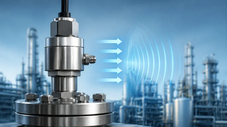
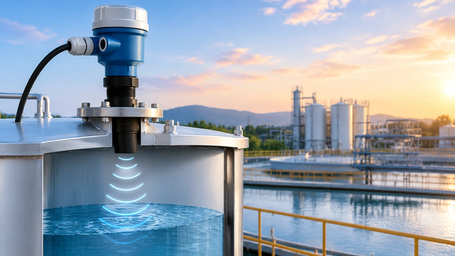
The fundamental operation of a level sensor ultrasonic is based on the "Time-of-Flight" (ToF) principle. The instrument consists of a transducer that acts as both a transmitter and a receiver.
The Acoustic Pulse
At regular intervals, the sensor's piezoelectric crystal is energized, causing it to vibrate and emit a burst of ultrasonic sound waves. These waves travel through the air or gas medium in the tank toward the material surface. When the sound waves encounter a change in density—such as the transition from air to liquid—a portion of the acoustic energy is reflected back toward the sensor as an echo.
Calculation of Distance
The sensor’s internal microprocessor measures the exact time interval between the emission of the pulse and the reception of the echo. Since the speed of sound in air is known, the distance ($D$) from the sensor to the material surface is calculated using the formula:
$$D = \frac{v \times t}{2}$$
Where:
* $v$ is the velocity of sound in the medium.
* $t$ is the total transit time (round trip).
To determine the actual level of the material ($L$), the measured distance is subtracted from the total tank height ($H$), which is calibrated during setup: $L = H – D$.
Temperature Compensation
The speed of sound is not constant; it varies significantly with the temperature of the medium through which it travels. In air, the speed of sound changes by approximately 0.17% per degree Celsius. To maintain accuracy, high-quality ultrasonic sensors incorporate an integrated temperature probe to measure the ambient air temperature and automatically adjust the distance calculation in real-time.
Key Components and Construction
A standard industrial ultrasonic level transmitter typically comprises three main sections:
1. The Transducer Face: Often constructed from PVDF (Polyvinylidene fluoride), ETFE, or UPVC, the transducer face must be chemically compatible with the vapors present in the tank. It is the vibrating element that generates the acoustic signal.
2. The Electronic Module: This contains the signal processing circuitry, which filters out background noise (false echoes) and converts the time-of-flight data into a standard industrial output, such as 4-20mA, HART, or RS485 Modbus.
3. The Housing: Industrial sensors are usually rated IP65 to IP68. For hazardous environments, explosion-proof or intrinsically safe housings are required to meet ATEX or IECEx standards.
Selection Criteria for Industrial Applications
Choosing the correct level sensor ultrasonic requires an analysis of the physical and chemical properties of the application. The following table provides a generalized selection framework based on common industrial parameters.
Selection Table: Ultrasonic Sensor Capabilities
| Parameter | Typical Range/Value | Notes for Selection |
| :— | :— | :— |
| Measurement Range | 0.1 m to 30 m (0.3 ft to 98 ft) | Longer ranges require lower frequency transducers (e.g., 20 kHz). |
| Accuracy | ±0.25% to ±0.5% of span | Accuracy depends on stable temperature and air composition. |
| Process Temperature | -40°C to +95°C (-40°F to 203°F) | High temperatures can distort the sound wave and damage the transducer. |
| Process Pressure | 0.5 bar to 3 bar (7.2 psi to 43.5 psi) | Ultrasonic waves do not travel in a vacuum and are attenuated at high pressures. |
| Output Signal | 4-20mA, HART, Modbus, Relays | Choose based on the integration requirements with PLC/SCADA systems. |
| Beam Angle | 5° to 12° | Narrower beam angles are better for narrow tanks with internal obstructions. |
For complex installations or specialized requirements, it is recommended to Review product options and application support to ensure the selected hardware aligns with site-specific engineering standards.
Installation Guidelines and Best Practices
The performance of a level sensor ultrasonic is heavily dependent on its physical placement. Improper installation is the leading cause of signal loss and measurement errors.
1. The Dead Zone (Blanking Distance)
Every ultrasonic sensor has a "dead zone" immediately below the transducer face, typically ranging from 100 mm to 800 mm (4 in to 31 in) depending on the frequency. Within this zone, the transducer cannot receive an echo because it is still vibrating from the transmission. The sensor must be mounted high enough so that the maximum liquid level never enters this dead zone.
2. Positioning and Orientation
* Perpendicularity: The sensor must be mounted perfectly perpendicular to the liquid surface. A tilt of even a few degrees can cause the reflected echo to miss the transducer entirely, resulting in a "Lost Echo" error.
* Wall Distance: To avoid interference from side-wall reflections, the sensor should be placed at a distance from the tank wall at least 1/6th of the tank diameter.
* Obstructions: The acoustic beam expands as it travels. Ensure that there are no ladders, pipes, or agitator blades within the "beam cone." If obstructions are unavoidable, many modern sensors offer "False Echo Suppression" software to ignore these static reflections.
3. Turbulence and Foam
Heavy turbulence can scatter the sound waves, while thick foam can absorb them. In such cases, the use of a stilling well (a vertical pipe that stabilizes the liquid surface) can provide a clear path for the ultrasonic signal.
Advantages and Limitations
Advantages
* Non-Contact: Since the sensor does not touch the medium, it is ideal for corrosive, viscous, or abrasive fluids. This also eliminates the risk of clogging or coating that affects hydrostatic or float-based sensors.
* Versatility: Capable of measuring both liquids and bulk solids (though solids require more careful aiming due to the angle of repose).
* Maintenance: With no moving parts, the wear and tear are minimal, leading to long service lives in harsh environments.
Limitations
* Vapor and Dust: High concentrations of heavy vapors or thick dust can attenuate the sound signal, reducing the effective range.
* Vacuum: Ultrasonic waves require a medium (air/gas) to travel. They cannot function in a vacuum.
* Surface Conditions: Extremely light, airy foam may absorb the signal, leading to inaccurate readings or signal loss. In these specific scenarios, radar level meters are often a preferred alternative.
Comparison: Ultrasonic vs. Radar Level Measurement
While ultrasonic sensors are excellent for many applications, it is helpful to understand how they compare to radar technology, which is also offered by manufacturers like Welk.
| Feature | Ultrasonic Level Sensor | Radar Level Meter (GWR/Non-Contact) |
| :— | :— | :— |
| Medium | Sound Waves (Mechanical) | Electromagnetic Waves (Radio) |
| Vacuum Performance | Cannot function | Excellent performance |
| Cost | Generally lower | Generally higher |
| Sensitivity to Vapor | High | Low |
| Temperature Limit | Typically < 95°C | Can exceed 400°C |
Maintenance and Troubleshooting
While a level sensor ultrasonic is largely maintenance-free, periodic inspections ensure long-term reliability:
* Transducer Cleaning: In applications with high humidity or splashing, condensation or crystals may form on the transducer face. Gently wiping the face with a soft cloth and mild solvent (if chemically compatible) will restore signal strength.
* Cable Integrity: Ensure that cable glands are tight and that there is no moisture ingress into the electronic housing.
* Signal Monitoring: If the output fluctuates wildly, check for new obstructions in the tank or changes in the chemical composition of the air space (e.g., increased vapor concentration).
Frequently Asked Questions (FAQ)
Q: Can an ultrasonic sensor measure the level of solids like sand or grain?
A: Yes, but with caveats. Solids often have an uneven surface (angle of repose) which scatters the sound waves. A sensor with a higher power output and a narrower beam angle is usually required, and the range is typically reduced by 50% compared to liquid measurements.
Q: How does wind affect an ultrasonic sensor in an open channel?
A: Strong winds can "blow" the sound wave away from the receiver or cause rapid temperature fluctuations. For outdoor open-channel flow or tank measurement, a sunshield and a protective shroud are recommended to stabilize the environment around the sensor.
Q: Is it possible to use an ultrasonic sensor in a pressurized tank?
A: Ultrasonic sensors can operate in slightly pressurized environments (typically up to 3 bar). However, as pressure increases, the speed of sound changes, and the transducer's ability to vibrate efficiently is dampened. For high-pressure vessels, radar or hydrostatic transmitters are more suitable.
Conclusion
The level sensor ultrasonic remains one of the most versatile and cost-effective tools in the industrial instrumentation toolkit. By understanding the physics of sound propagation and adhering to strict installation guidelines regarding the dead zone and beam angle, engineers can achieve high levels of accuracy and reliability. Whether managing water resources or monitoring chemical inventory, Welk provides the technical expertise and hardware necessary to optimize these systems for global industrial standards. For detailed specifications and to find the right model for your specific process conditions, visit the Main Page to explore our full range of level measurement solutions.