Level Ultrasonic Sensor
Level Ultrasonic Sensor
In the landscape of industrial process control, the level ultrasonic sensor has established itself as a cornerstone technology for non-contact measurement. As industries move toward higher levels of automation and precision, understanding the fundamental physics, selection criteria, and installation nuances of these instruments is essential for plant engineers and system integrators. This guide provides a technical deep dive into ultrasonic level measurement, offering practical insights for its application in water treatment, chemical processing, and general industrial automation.
1. Measurement Principles of Ultrasonic Technology
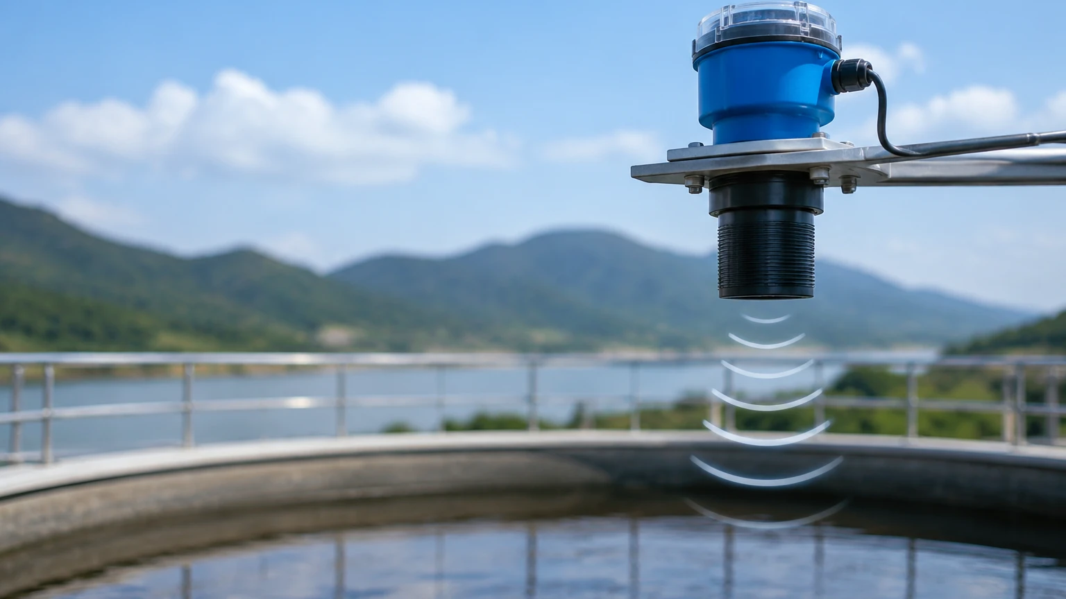
The operation of a level ultrasonic sensor is based on the "Time-of-Flight" (ToF) principle. The sensor’s transducer emits high-frequency acoustic pulses—typically in the range of 20 kHz to 80 kHz—directed toward the surface of the medium being measured. These sound waves travel through the air, reflect off the material surface, and return to the transducer.
The Time-of-Flight Calculation
The distance between the sensor and the material surface is calculated using the following formula:
D = (c × t) / 2
Where:
* D is the distance to the surface.
* c is the speed of sound in the specific medium (usually air).
* t is the total time elapsed between pulse emission and echo reception.
Since the pulse must travel to the surface and back, the total distance is divided by two. To determine the actual level of the material in a tank, the measured distance (D) is subtracted from the total tank height (H) established during calibration (Level = H – D).
The Impact of Temperature
The speed of sound is not a constant; it varies significantly with the temperature of the medium through which it travels. In air, the speed of sound changes by approximately 0.17% per degree Celsius. To maintain accuracy, modern level ultrasonic sensors, such as those manufactured by Welk, incorporate an integrated temperature sensor. This allows the internal microprocessor to perform real-time compensation, ensuring that fluctuations in ambient temperature do not skew the level readings.
2. Key Components and Construction
A professional-grade level ultrasonic sensor consists of several critical components designed to withstand industrial environments:
1. Transducer (The Heart): Utilizing the piezoelectric effect, the transducer converts electrical energy into mechanical vibrations (sound) and vice versa. The material of the transducer face (e.g., PVDF, ETFE, or UPVC) determines its chemical resistance.
2. Electronic Module: This unit controls pulse generation, signal processing, and echo evaluation. Advanced algorithms are employed here to filter out "false echoes" caused by internal tank obstructions like ladders or agitators.
3. Housing: Usually rated IP66, IP67, or IP68, the housing protects the electronics from moisture, dust, and corrosive vapors. Materials range from reinforced plastics for water applications to stainless steel for more demanding environments.
4. Signal Output: Standard industrial interfaces include 4-20mA analog signals (often with HART protocol), RS485 (Modbus), or digital switches for point-level detection.
3. Practical Selection Criteria
Choosing the correct level ultrasonic sensor requires a detailed analysis of the application environment. Engineers should consult the Main Page of the manufacturer's technical catalog to compare specific model capabilities against project requirements.
Technical Specification Table
| Parameter | Typical Industrial Range | Engineering Consideration |
| :— | :— | :— |
| Measuring Range | 0.25m to 30m | Choose a range 20% greater than the tank height. |
| Dead Zone (Blocking Distance) | 0.2m to 0.6m | The area directly below the sensor where measurement is impossible. |
| Accuracy | ±0.25% to ±0.5% of span | Higher frequency sensors generally offer better precision. |
| Beam Angle | 6° to 12° | Narrower angles are better for tall, narrow tanks. |
| Operating Pressure | -0.02 to 0.3 MPa | Ultrasonic waves do not travel in a vacuum. |
| Process Temperature | -40°C to +70°C | High temperatures can cause signal attenuation. |
Medium Characteristics
* Liquids: Ideal for water, wastewater, oils, and most chemicals. However, heavy foam can absorb the ultrasonic pulse, leading to signal loss.
* Solids: Can be used for grain or plastic pellets, but the irregular surface of solids scatters the sound waves. A sensor with a higher power output and a lower frequency is typically required for solids compared to liquids.
4. Installation Best Practices
Correct installation is the most critical factor in ensuring the reliability of a level ultrasonic sensor. Poor placement is the leading cause of "lost echoes" and erratic readings.
Positioning and Clearance
* Avoid the Dead Zone: The sensor must be mounted at a height such that the maximum liquid level never enters the "blocking distance" or dead zone. If the liquid reaches this zone, the sensor will report a false distance or an error.
* Perpendicularity: The sensor face must be perfectly parallel to the liquid surface. A tilt of even a few degrees can cause the reflected signal to bounce away from the transducer rather than back to it.
* Wall Clearance: Do not mount the sensor too close to the tank wall. The acoustic beam spreads as it travels (the beam angle). If the beam hits the tank wall, it creates parasitic echoes. A general rule is to maintain a distance from the wall of at least 1/10th of the tank height.
Obstruction Management
Internal structures such as fill pipes, cooling coils, or support beams can interfere with the signal. While many Welk sensors feature "False Echo Suppression" software to ignore these static objects, it is best practice to install the sensor in a location with a clear line of sight to the material surface.
Standpipe Installation
In tanks where foam or turbulence is present, or where the mounting nozzle is very long, a standpipe (still-well) can be used. The pipe acts as a waveguide, focusing the signal and protecting the surface from agitation. When using a standpipe, the pipe must be smooth and free of burrs on the inside.
5. Environmental Limitations and Mitigation
While highly versatile, the level ultrasonic sensor is not a universal solution. Understanding its physical limits prevents costly engineering errors.
1. Vacuum Conditions: Sound requires a medium to travel. In a vacuum or high-vacuum environment, ultrasonic sensors cannot function. Radar level meters are the preferred alternative here.
2. Heavy Dust and Steam: Dense dust (in silos) or heavy steam (in hot water tanks) can attenuate the sound pulse. In these cases, lower frequency sensors (which have more "punch") or high-frequency radar should be considered.
3. Pressure Extremes: High pressure changes the density of the air, which in turn changes the speed of sound. While compensation is possible, ultrasonic sensors are generally limited to near-atmospheric pressure applications.
4. Surface Turbulence: Rapidly splashing liquids or heavy surface agitation can scatter the signal. Using the software's damping functions or a stilling well can mitigate this issue.
6. Maintenance and Troubleshooting
One of the primary benefits of a non-contact level ultrasonic sensor is the minimal maintenance required, as no parts are submerged in the process media. However, periodic checks are recommended.
* Transducer Cleaning: In applications with condensing vapors or splashing, buildup can occur on the transducer face. This should be cleaned gently with a soft cloth and water or a mild detergent. Avoid abrasive tools that could scratch the piezoelectric surface.
* Cable Integrity: Ensure that the cable entry is sealed correctly to prevent moisture ingress into the housing, which can lead to electronic failure.
Common Troubleshooting Steps
* Reading stays at maximum: This often indicates the sensor is not receiving an echo. Check for obstructions or check if the medium has entered the dead zone.
* Unstable Readings: Often caused by surface turbulence or electrical interference. Check the grounding of the sensor and the shielding of the signal cable.
* Incorrect Level: Usually a calibration issue or a failure of the temperature compensation. Verify the "Empty Tank" distance setting in the sensor configuration.
7. Frequently Asked Questions (FAQs)
Q: Can an ultrasonic sensor measure the level of fuming acids?
A: Yes, provided the transducer face is made of a chemically resistant material like PVDF. However, heavy fumes can change the gas composition in the tank, affecting the speed of sound and requiring specific calibration.
Q: What is the difference between an integrated and a split-type sensor?
A: An integrated sensor has the transducer and electronics in a single housing. A split-type (remote) sensor separates the transducer from the controller/display unit, which is useful if the measurement point is difficult to access or subject to high vibration.
Q: How does a level ultrasonic sensor handle agitators?
A: Most modern instruments use software algorithms to map the tank. During an empty tank run, the sensor identifies the echoes from the agitator blades and "masks" them, only tracking the echo that moves (the liquid level).
Q: Is it possible to use these sensors for open channel flow measurement?
A: Yes. By measuring the head (level) of water moving through a flume or weir and applying a programmed flow formula, the level ultrasonic sensor can accurately calculate flow rates in cubic meters per hour ($m^3/h$).
For engineers seeking reliable, cost-effective, and accurate measurement solutions, the level ultrasonic sensor remains a top-tier choice for a wide range of industrial applications. By adhering to proper selection and installation guidelines, users can ensure long-term operational stability and process safety.