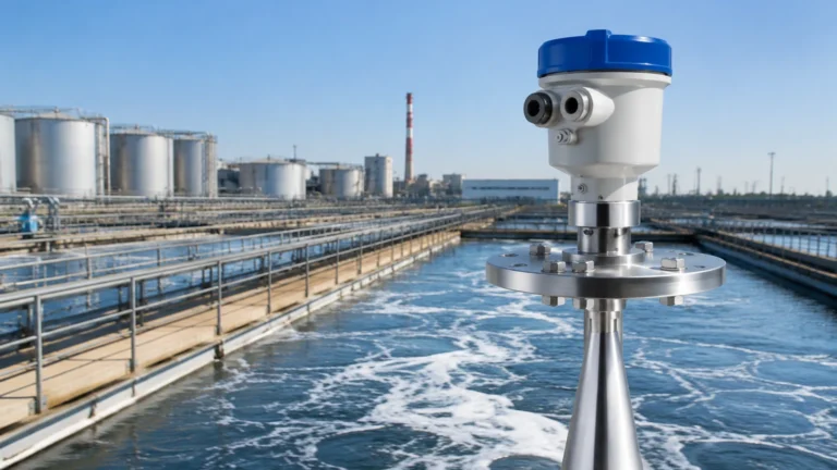
Liquid Flow Detector
Liquid Flow Detector
In industrial process control, a liquid flow detector serves as a critical safeguard and monitoring tool. Unlike complex flow meters that provide continuous volumetric data, a liquid flow detector—often referred to as a flow switch or flow sensor—is primarily designed to detect the presence, absence, or velocity threshold of a fluid within a pipeline. These devices are essential for protecting expensive equipment such as pumps, motors, and heat exchangers from damage caused by dry running or insufficient cooling.
For engineers and plant managers, selecting the correct liquid flow detector requires a deep understanding of fluid dynamics, material compatibility, and the specific mechanical principles that govern different detection technologies. This guide provides a technical overview of how these instruments operate, how to select the right model for specific industrial environments, and the best practices for installation and maintenance.
Measurement Principles of Liquid Flow Detectors
To choose the right instrument, one must first understand the physics behind the detection. Liquid flow detectors generally fall into mechanical, thermal, or electronic categories.
Thermal Dispersion Principle
Thermal flow detectors utilize the heat transfer properties of the moving fluid. The sensor probe typically contains two thermistors: one is heated to a constant temperature, and the other serves as a reference, measuring the ambient temperature of the liquid. When the liquid is stationary, the temperature difference between the two sensors is at its maximum. As the liquid begins to flow, it carries heat away from the heated sensor. This cooling effect is proportional to the flow velocity. The electronics translate this change in temperature differential into a switching signal or a linear output.
Paddle and Vane (Mechanical) Principle
This is one of the oldest and most reliable methods for flow detection. A paddle or vane is suspended in the flow stream. As the liquid moves, it exerts dynamic pressure on the paddle, pushing it forward. This mechanical movement is transmitted—often via a magnetic coupling to isolate the fluid from the electronics—to a microswitch or reed switch. These are ideal for "flow/no-flow" applications where high precision is less critical than robust, mechanical reliability.
Magnetic-Inductive Principle
Based on Faraday’s Law of Induction, these detectors are used for conductive liquids. As a conductive fluid moves through a magnetic field generated by the sensor, it induces a voltage. This voltage is directly proportional to the flow velocity. Because this method requires no moving parts and creates no obstruction in the pipe, it is highly resistant to wear and pressure loss.
Ultrasonic (Transit-Time and Doppler)
Ultrasonic detectors use sound waves to determine flow. Transit-time sensors send signals back and forth; the time difference between the signal traveling with the flow and against it indicates the speed. Doppler sensors, conversely, bounce signals off particles or bubbles in the liquid. These are often used as non-invasive "clamp-on" detectors, allowing for installation without cutting into the pipework.
Key Evaluation Criteria for Selection
Selecting a liquid flow detector is not a "one-size-fits-all" process. The following factors must be evaluated to ensure long-term accuracy and device longevity:
1. Fluid Properties: Is the liquid corrosive, abrasive, or viscous? For example, a paddle switch may fail in highly abrasive slurries, whereas a non-contact ultrasonic or magnetic-inductive sensor would thrive.
2. Conductivity: If using a magnetic-inductive detector, the liquid must have a minimum conductivity (usually >5 μS/cm). Non-conductive liquids like demineralized water or hydrocarbons require thermal or mechanical sensors.
3. Flow Range and Set Point: Determine the minimum and maximum flow rates. The detector must be sensitive enough to trip at the required low-flow safety limit without being damaged by high-velocity surges.
4. Process Conditions: Ensure the sensor materials (316L stainless steel, Hastelloy, PTFE, etc.) can withstand the operating pressure (measured in bar or PSI) and temperature (Celsius or Fahrenheit).
5. Pipe Size: Detectors are designed for specific pipe diameters. While some are "insertion type" for large pipes, others are "in-line" units with specific thread or flange connections.
Comparison Table: Flow Detection Technologies
| Technology | Suitable Fluids | Advantages | Limitations |
| :— | :— | :— | :— |
| Thermal | Clean liquids, oils, water | No moving parts, high sensitivity | Sensitive to scale/buildup |
| Paddle | Water, non-viscous fluids | Low cost, simple operation | Mechanical wear, pressure drop |
| Magnetic | Conductive liquids, slurries | No obstruction, very durable | Requires conductivity, higher cost |
| Ultrasonic | Clean (Transit) / Dirty (Doppler) | Non-invasive, no pressure drop | Requires stable flow profile |
| Hydrostatic | Water, chemicals | Reliable for tank levels/flow | Indirect measurement |
Installation Considerations and Best Practices
Even the most advanced liquid flow detector will fail if installed incorrectly. To ensure a stable flow profile and accurate detection, engineers should adhere to the following guidelines:
Straight Pipe Requirements
Turbulence is the enemy of accurate flow detection. Valves, elbows, and pumps create swirls and eddies that can cause a detector to chatter or give false readings. A general rule of thumb is to allow for 10D (ten times the pipe diameter) of straight pipe upstream and 5D of straight pipe downstream from the sensor location.
Orientation and Positioning
* Horizontal Pipes: This is the preferred orientation. For liquids, the sensor should ideally be mounted on the side or bottom of the pipe to ensure it remains submerged and to avoid air pockets trapped at the top.
* Vertical Pipes: If installing in a vertical line, the flow must be upward. This ensures the pipe remains completely full of liquid. Downward flow can lead to partial filling or vacuum conditions, which result in erratic sensor behavior.
Electrical and Signal Integration
Modern detectors offer various outputs, including SPDT relay contacts, PNP/NPN transistors, or 4-20mA analog signals. Ensure the electrical housing (e.g., IP65, IP67, or NEMA 4X) matches the environment. In hazardous areas, explosion-proof (Ex-d) or intrinsically safe (Ex-i) certifications are mandatory.

Limitations and Common Risks
While highly effective, liquid flow detectors have specific limitations that must be managed:
* Entrained Air: Air bubbles in a liquid line can cause thermal sensors to overheat or ultrasonic transit-time sensors to lose signal. Proper venting and air elimination are necessary.
* Fouling and Coating: In applications like wastewater or chemical processing, material can build up on the sensor probe. This "coating" acts as an insulator for thermal sensors and can jam mechanical paddles. Regular maintenance or the use of flush-mounted sensors can mitigate this.
* Cavitation: If the pressure drops too low, vapor bubbles form and collapse, which can physically erode the sensor hardware over time.
* Minimum Velocity: Most detectors have a "dead zone" or a minimum velocity below which they cannot reliably detect movement. If your application involves extremely slow seepage, a specialized low-flow thermal sensor is required.
Frequently Asked Questions (FAQs)
Q: Can a liquid flow detector be used for gas applications?
A: Some technologies, like thermal dispersion, are excellent for both liquids and gases. However, mechanical paddle switches are usually calibrated for the density of water and may not respond to gas flow unless specifically designed for high-velocity air.
Q: How often should a flow detector be calibrated?
A: For safety-critical applications (like pump dry-run protection), an annual functional test is recommended. For process monitoring, calibration intervals depend on the fluid's corrosivity and the presence of solids.
Q: What is the difference between a flow switch and a flow transmitter?
A: A flow switch (detector) provides a binary output (on/off) at a specific set point. A flow transmitter provides a continuous signal (like 4-20mA) that represents the actual flow rate across a range.
Q: Why is my paddle switch not resetting?
A: This is often caused by debris trapped in the hinge of the paddle or a weakened return spring. In some cases, magnetic particles in the fluid can interfere with the magnetic coupling used to trigger the internal switch.
Conclusion and Next Steps
Implementing a robust liquid flow detector is a fundamental step in ensuring industrial operational safety and efficiency. By matching the measurement principle to the chemical and physical properties of the fluid, and adhering to strict installation standards, facilities can prevent catastrophic equipment failure and reduce unplanned downtime.
For those seeking to integrate these sensors into a broader automation strategy, it is essential to consult with manufacturers who offer a range of technologies, from radar and ultrasonic to hydrostatic and mechanical solutions. For detailed product specifications and technical support in choosing the right instrumentation for your project, please visit our Main Page to review product options and application support.