Magmeter Flow
Magmeter Flow
In the landscape of industrial process control, magmeter flow measurement stands as one of the most reliable and versatile technologies for handling conductive liquids. Often referred to as electromagnetic flowmeters, these devices are essential components in systems where accuracy, longevity, and minimal pressure drop are prioritized. For engineers and facility managers, understanding the nuances of magmeter flow is critical for optimizing operations in water treatment, chemical processing, and industrial automation.
While level measurement instruments—such as those found on the Main Page of specialized manufacturers like Welk—provide critical data on volume and inventory, magmeter flow sensors provide the real-time velocity and volumetric data necessary for dynamic process control. This article explores the principles, selection criteria, and installation requirements for magmeter flow technology.
Understanding the Principles of Electromagnetic Flow Measurement
The operation of a magmeter flow system is based on Faraday’s Law of Electromagnetic Induction. This principle states that a conductor moving through a magnetic field produces an electrical signal within the conductor, which is directly proportional to the velocity of the moving conductor.
In the context of a flowmeter, the "conductor" is the process liquid itself. For the technology to function, the liquid must have a minimum level of electrical conductivity, typically at least 5 μS/cm (microsiemens per centimeter).
The Mathematical Foundation
The relationship is defined by the equation:
E = kBDv
Where:
* E is the voltage generated (the signal).
* k is a constant specific to the device.
* B is the strength of the magnetic field.
* D is the distance between the electrodes (usually the inner diameter of the pipe).
* v is the velocity of the liquid.
Because the magnetic field (B) and the distance (D) are fixed by the meter’s construction, the induced voltage is directly proportional to the flow velocity. The transmitter then converts this low-voltage signal into a standard output, such as 4-20mA, pulse, or digital protocols like Modbus or HART.
Essential Components of a Magmeter Flow System
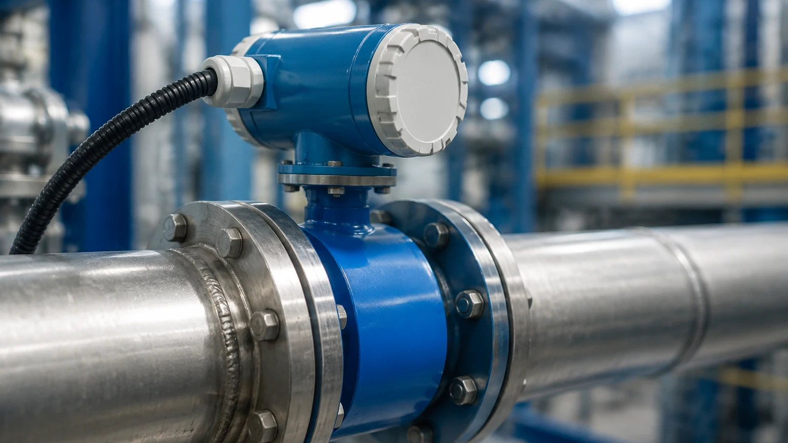
A magmeter flow assembly consists of two primary parts: the sensor (the flow tube installed in the pipeline) and the transmitter (the electronic brain that processes the signal).
1. The Flow Tube
The flow tube is a non-magnetic section of pipe, typically lined with an insulating material. It contains two electromagnetic coils that generate the magnetic field and two or more electrodes that pick up the voltage generated by the flowing fluid.
2. The Liner
Since the pipe wall is often metallic, an insulating liner is required to prevent the generated voltage from shorting out into the pipe. The choice of liner material is critical for chemical compatibility and temperature resistance.
3. The Electrodes
Electrodes are the contact points that sense the induced voltage. They must be constructed from materials that can withstand the corrosiveness of the process media without losing conductivity.
4. The Transmitter
The transmitter can be mounted directly on the sensor (integral) or located remotely. It filters out electrical noise, compensates for fluctuations in the power supply, and provides the user interface for calibration and diagnostics.
Technical Selection Criteria for Industrial Applications
Selecting the right magmeter flow device requires a detailed analysis of the process conditions. Unlike level sensors, which may be non-contact (like radar or ultrasonic), magmeters are wetted instruments, meaning every internal component must be compatible with the fluid.
Liner Material Selection
The liner is the most vulnerable part of the meter. Common materials include:
| Liner Material | Temperature Range | Characteristics | Typical Applications |
| :— | :— | :— | :— |
| PTFE (Teflon) | -20°C to 120°C | High chemical resistance, anti-adhesive | Strong acids, bases, chemicals |
| PFA | -20°C to 180°C | Better vacuum resistance than PTFE | High-temp chemicals, food/pharma |
| Hard Rubber | 0°C to 80°C | Abrasion resistant, economical | Water treatment, wastewater |
| Polyurethane | -20°C to 60°C | Extremely abrasion resistant | Slurries, mining, sand-laden water |
Electrode Material Selection
Electrodes must be chosen to prevent corrosion and "noise" in the signal. Standard options include:
* 316L Stainless Steel: Suitable for mildly corrosive liquids and water.
* Hastelloy C: Used for more aggressive chemicals and sea water.
* Titanium: Excellent for salt water and chloride-rich environments.
* Tantalum: Reserved for the most aggressive acids, such as hydrochloric or sulfuric acid.
Integrating Magmeter Flow with Level Measurement Solutions
In many industrial setups, magmeter flow data is used in conjunction with level measurement to achieve mass balance and leak detection. For instance, in a large storage tank application, a Welk radar level meter provides the static volume of the vessel, while a magmeter flow sensor at the inlet and outlet monitors the dynamic movement of the product.
By comparing the change in level (volume) over time against the integrated flow rate from the magmeter, operators can identify discrepancies that might indicate a leak, a faulty valve, or a calibration error in one of the instruments. This dual-layered approach is a hallmark of robust industrial automation.
Installation Best Practices and Considerations
The accuracy of a magmeter flow system is heavily dependent on the installation environment. Even the most advanced meter will fail to provide accurate data if installed incorrectly.
1. The "Full Pipe" Requirement
Magmeters can only measure accurately if the pipe is completely full of liquid. If there is air in the pipe, the meter will read the velocity of the liquid but assume the entire cross-section is full, leading to significant over-reporting of flow. In gravity-fed systems, a "U-trap" or a vertical upward flow orientation is recommended to ensure the sensor remains flooded.
2. Straight Pipe Runs
To ensure a stable, non-turbulent flow profile, magmeters require a certain amount of straight pipe before and after the sensor. The industry standard is typically:
* Upstream: 5 times the pipe diameter (5D).
* Downstream: 2 times the pipe diameter (2D).
If the meter is installed too close to a pump, valve, or elbow, the resulting turbulence will cause the flow signal to fluctuate wildly.
3. Grounding and Electrical Noise
Because the voltage signals generated in magmeter flow measurement are in the millivolt range, they are highly susceptible to electrical interference. Proper grounding is non-negotiable.
* In metallic pipes: The meter should be bonded to the pipe flanges.
* In plastic or lined pipes: Grounding rings must be installed between the meter and the pipe flanges to provide a path to the fluid's electrical potential.
Limitations and Common Application Risks
While magmeter flow technology is robust, it is not a "one-size-fits-all" solution. Engineers must be aware of the following limitations:
* Conductivity Limits: Magmeters cannot measure oils, hydrocarbons, distilled water, or gases, as these fluids do not have the necessary electrical conductivity to generate a signal.
* Vacuum Conditions: Some liners, particularly PTFE, can collapse or be sucked away from the pipe wall if the system experiences a vacuum. PFA liners with stainless steel mesh reinforcement are preferred for vacuum applications.
* Entrained Air: Large bubbles or foam can cause the signal to drop out or become erratic. If air entrainment is unavoidable, an air eliminator should be installed upstream.
* Scaling and Coating: If the process liquid tends to leave deposits (like calcium carbonate or grease), the electrodes may become insulated, leading to a loss of signal. Some modern magmeters include electrode cleaning circuits or ultrasonic cleaning options to mitigate this.
Frequently Asked Questions (FAQ)
Q: Can a magmeter flow sensor measure flow in both directions?
A: Yes, most modern electromagnetic flowmeters are inherently bi-directional. They can be configured to provide separate totals for forward and reverse flow, which is useful in applications like reservoir management.
Q: How often does a magmeter need calibration?
A: Because there are no moving parts to wear out, magmeters are extremely stable. In many water applications, a verification check every 1–2 years is sufficient. However, in corrosive or abrasive applications, more frequent inspections of the liner and electrodes are recommended.
Q: What is the typical accuracy of a magmeter flow system?
A: High-quality industrial magmeters typically offer an accuracy of ±0.5% of the flow rate. High-precision models can achieve ±0.2%.
Q: Can I install a magmeter in a vertical pipe?
A: Yes, provided the flow is moving upward. This ensures the pipe remains full. Vertical downward flow is generally discouraged because it is difficult to guarantee a full pipe without significant backpressure.
By adhering to these engineering principles and selection guidelines, B2B stakeholders can ensure that their magmeter flow installations provide the reliable, long-term data required for modern industrial processes. When combined with the high-precision level measurement solutions available through Welk's Main Page, facilities can achieve a comprehensive and accurate view of their fluid dynamics.