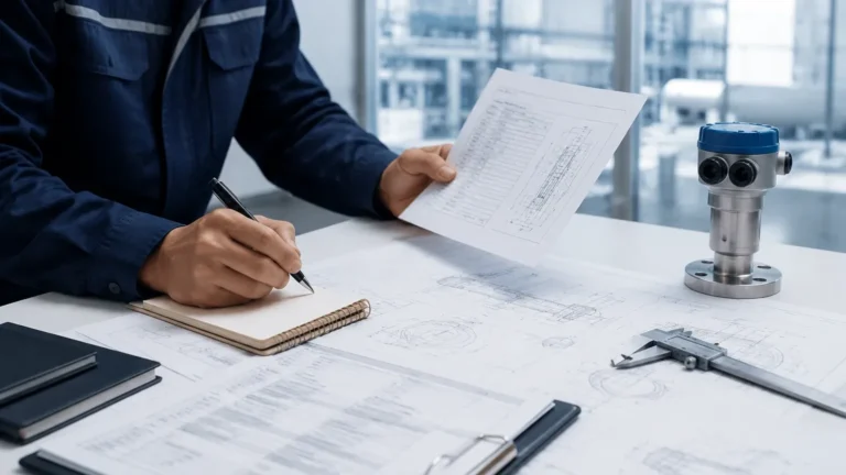
Metering Stations
Metering Stations
In the complex landscape of industrial fluid management, metering stations serve as the critical nodes where the quantity, quality, and composition of fluids are precisely measured. Often referred to as the "cash registers" of the oil, gas, and water industries, these stations are essential for custody transfer, fiscal accounting, and process optimization. While flow measurement is the primary function of these facilities, level measurement plays an equally vital role in ensuring the accuracy and safety of the entire system. From monitoring separator vessels to managing condensate tanks and chemical injection skids, reliable level instrumentation is the backbone of efficient metering station operations.
Selecting the right level measurement technology requires a deep understanding of the physical principles at play, the characteristics of the media being measured, and the specific environmental conditions of the site. This guide explores the fundamental measurement principles, selection criteria, and installation best practices for level instruments within industrial metering stations.
Understanding the Role of Level Measurement in Metering Stations
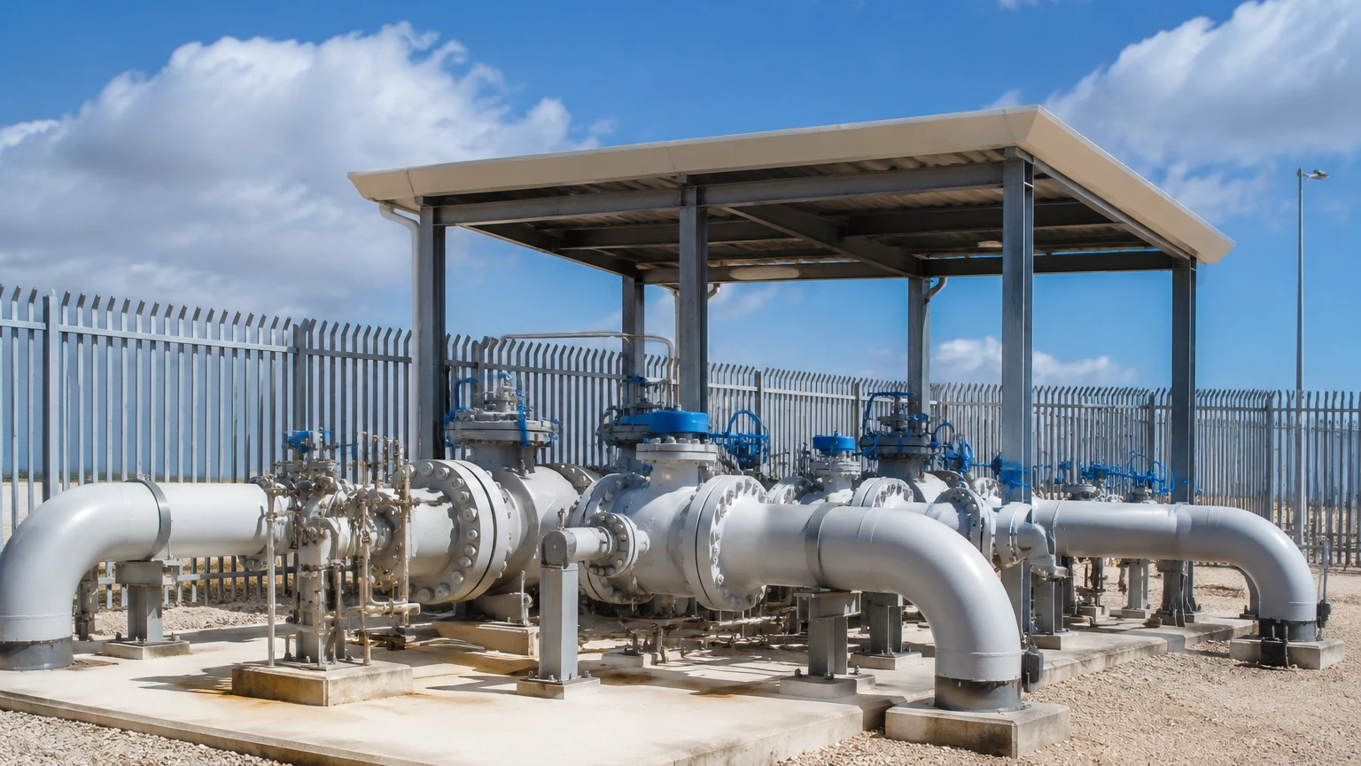
Metering stations are more than just a collection of flow meters. They are integrated systems designed to handle fluids under varying pressures and temperatures. Within these stations, level measurement is required in several key areas:
1. Separator Vessels: In oil and gas applications, separators divide the well stream into gas, oil, and water. Level sensors are required to monitor the interfaces between these fluids to ensure clean separation and prevent carryover.
2. Surge and Buffer Tanks: These tanks stabilize the flow before it enters the primary metering run. Maintaining a consistent level prevents pump cavitation and ensures a steady pressure profile.
3. Condensate and Drain Tanks: Metering stations often produce liquid fallout (condensate). Level switches and transmitters monitor these tanks to trigger automated drainage or alert operators to high-level risks.
4. Chemical Injection Skids: To prevent corrosion or hydrate formation, chemicals are often injected into the stream. Level sensors ensure the chemical supply is adequate and track consumption rates.
For engineers and operators looking to optimize these processes, visiting the Main Page of a dedicated instrumentation provider offers a starting point for exploring specific hardware solutions.
Core Measurement Principles for Industrial Level Sensors
Before selecting an instrument for metering stations, it is essential to understand how different technologies interact with the process media. The most common principles used in modern industrial level measurement include radar, ultrasonic, hydrostatic, and magnetic detection.
Radar Level Measurement (ToF)
Radar technology operates on the Time-of-Flight (ToF) principle. The sensor emits a high-frequency electromagnetic pulse (typically in the GHz range) that travels to the surface of the medium, reflects, and returns to the sensor. The distance is calculated based on the time interval between emission and reception.
* Non-Contact Radar: These sensors emit pulses through the air. They are ideal for corrosive or high-temperature media because they do not touch the fluid. High-frequency radar (e.g., 80 GHz) provides a narrow beam angle, which is beneficial in narrow vessels or those with internal obstructions.
* Guided Wave Radar (GWR): This technology uses a physical probe (rod or cable) to guide the microwave pulse. GWR is highly effective for measuring interfaces (e.g., oil over water) and is less affected by foam or turbulence than non-contact radar.
Ultrasonic Level Measurement
Similar to radar, ultrasonic sensors use the ToF principle but employ sound waves instead of electromagnetic pulses. The sensor emits an ultrasonic pulse that reflects off the liquid surface.
Because sound speed is affected by air temperature, these sensors include integrated temperature compensation. However, they are sensitive to vacuum conditions, high pressure, and heavy vapors, which can attenuate the sound signal. They are most commonly used in water treatment components of metering stations where conditions are relatively stable.
Hydrostatic Level Measurement
Hydrostatic sensors measure the pressure exerted by a liquid column. The principle is based on the formula:
*P = ρ × g × h*
(Where *P* is pressure, *ρ* is density, *g* is gravity, and *h* is the height of the liquid).
By measuring the pressure at the bottom of a tank and knowing the fluid's density, the level can be calculated with high precision. This is a robust, contact-based method frequently used in vented tanks or deep wells.
Magnetic Level Gauges
Magnetic gauges utilize a float containing a magnet that moves with the liquid level inside a bypass chamber. Outside the chamber, a series of magnetic flaps or a follower indicates the level visually. For B2B applications, these are often paired with a reed chain transmitter to provide a 4-20mA signal to the control room, combining visual local indication with remote monitoring.
Selecting Level Instruments for Metering Station Applications
Choosing the appropriate technology for metering stations depends on the fluid properties, vessel geometry, and accuracy requirements. The following table provides a comparative overview of the primary technologies.
| Technology | Accuracy | Media Suitability | Pressure/Temp Limits | Best Use Case |
| :— | :— | :— | :— | :— |
| Non-Contact Radar | ±1 mm to ±5 mm | Liquids, Slurries, Solids | High (up to 160 bar / 450°C) | Corrosive chemicals, large storage tanks |
| Guided Wave Radar | ±2 mm | Liquids, Interfaces | High (up to 400 bar / 450°C) | Oil/Water interface, foaming liquids |
| Ultrasonic | ±0.25% of range | Water-based liquids | Low (up to 3 bar / 80°C) | Open channels, water sumps |
| Hydrostatic | ±0.1% to ±0.5% | Clean liquids | Moderate (up to 40 bar / 100°C) | Fuel tanks, deep well monitoring |
| Magnetic Gauge | ±5 mm to ±10 mm | Clean liquids | High (up to 200 bar / 400°C) | Boiler drums, high-pressure bypass |
| Level Switches | N/A (Point) | Most liquids | High (varies by type) | Overfill protection, pump run-dry |
Installation Best Practices for Reliable Data
Even the most advanced level meter will fail if installed incorrectly. In the context of metering stations, where precision is paramount, the following installation guidelines should be followed:
1. Nozzle Geometry and Placement
For radar and ultrasonic sensors, the nozzle diameter and height are critical. If a nozzle is too long or narrow, the signal may reflect off the nozzle walls rather than the liquid surface (the "ringing" effect). Ideally, the sensor should be placed away from the tank wall—typically at 1/4 to 1/6 of the tank diameter—to avoid interference from wall reflections.
2. Avoiding Obstructions
Internal structures such as heating coils, ladders, or agitators can create false echoes. While modern software can "map out" these reflections, it is best to install the sensor in a clear path to the liquid surface. If obstructions are unavoidable, Guided Wave Radar is often the superior choice as the signal is confined to the probe.
3. Managing Turbulence and Foam
In separator vessels within metering stations, turbulence is common. Stilling wells or bypass chambers can be used to provide a calm surface for measurement. For foaming applications, low-frequency radar or hydrostatic transmitters are generally more reliable than ultrasonic or high-frequency radar, which may see the foam as the "top" of the liquid or lose the signal entirely.
4. Environmental Protection
Many metering stations are located in harsh environments, from offshore platforms to desert regions. Instruments should have a minimum IP67 or IP68 rating. Furthermore, in oil and gas stations, ATEX or IECEx explosion-proof certifications are mandatory for all electronic components.
Common Risks and Operational Limitations
While modern instrumentation is highly reliable, engineers must account for specific risks that can compromise data integrity at metering stations:
* Dielectric Constant (dk) Variations: Radar relies on the dielectric constant of the medium. If the dk is very low (e.g., liquefied gases), the signal reflection may be weak. In such cases, a stilling well or a specialized high-sensitivity GWR probe is required.
* Vapor and Condensation: Heavy steam or chemical vapors can slow down ultrasonic waves, leading to measurement errors. Condensation on the sensor face can also cause a "blind" condition. Radar is generally unaffected by vapors, but droplets on the antenna can still impact performance.
* Density Shifts: Hydrostatic pressure sensors assume a constant fluid density. If the temperature fluctuates significantly or the fluid composition changes (e.g., varying crude oil grades), the calculated level will be inaccurate unless compensated by a secondary temperature or density probe.
* Build-up and Scaling: In wastewater or heavy oil applications, material can build up on the sensor or probe. Non-contact radar is least affected by this, while float-based systems or GWR probes may require regular cleaning to prevent sticking or signal attenuation.
Frequently Asked Questions
Q: Can one level sensor handle all fluids in a metering station?
No single technology is universal. While non-contact radar is the most versatile, hydrostatic sensors are often more cost-effective for simple water tanks, and Guided Wave Radar is specifically required for accurate interface measurement in separators.
Q: How often should level meters in metering stations be calibrated?
For fiscal or custody transfer applications, annual calibration is standard. For general process monitoring, a check every 2-3 years may suffice, depending on the stability of the media and the criticality of the measurement.
Q: What is the "Dead Zone" in level measurement?
The dead zone (or blocking distance) is the area immediately below the sensor where it cannot measure. For ultrasonic sensors, this is typically 0.2m to 0.5m. For radar, it is much smaller, often only a few centimeters. This must be accounted for when designing tank height and overflow setpoints.
Q: Is wireless transmission suitable for metering stations?
Wireless HART or LoRaWAN transmitters are increasingly used for monitoring remote tanks where cabling costs are prohibitive. However, for safety-critical overfill protection, hard-wired connections are still preferred to ensure real-time response and compliance with SIL (Safety Integrity Level) requirements.
Conclusion
Level measurement is a fundamental component of the modern metering station, providing the data necessary for safety, efficiency, and financial accuracy. By understanding the principles of radar, ultrasonic, and hydrostatic measurement, and by adhering to rigorous installation standards, operators can ensure their facilities run at peak performance. For those seeking technical specifications or customized OEM/ODM solutions for their specific industrial automation needs, reviewing product options and application support on the Main Page is a recommended next step in the procurement process.