Non Invasive Flow Measurement
Non Invasive Flow Measurement
In the landscape of industrial process control, the ability to measure fluid movement without breaching the integrity of the piping system has become a cornerstone of modern efficiency. Non invasive flow measurement, primarily achieved through clamp-on ultrasonic technology, allows engineers to capture high-precision data without the downtime, pressure drops, or contamination risks associated with traditional inline meters. This methodology is particularly vital in sectors where process continuity is non-negotiable, such as chemical processing, water treatment, and oil and gas production.
Selecting the appropriate non-invasive solution requires a deep understanding of acoustic physics and the mechanical properties of the conduit. Unlike wetted sensors, non-invasive instruments must transmit signals through pipe walls and internal liners, making the selection process more complex than simply matching a line size. This guide provides a technical overview of the principles, selection criteria, and installation requirements for non-invasive flow systems.
Principles of Non-Invasive Flow Measurement
Non-invasive flow measurement is almost exclusively synonymous with ultrasonic technology. These instruments utilize transducers clamped to the exterior of a pipe to send and receive ultrasonic pulses through the fluid. There are two primary physical principles used: Transit-Time and Doppler Effect.
Transit-Time Ultrasonic Principle
Transit-time measurement relies on the difference in the time it takes for an ultrasonic pulse to travel between two transducers. One transducer sends a signal upstream, and the other sends a signal downstream. Because the fluid is moving, the pulse traveling with the flow (downstream) moves faster than the pulse traveling against the flow (upstream).
The time difference ($Δt$) is directly proportional to the flow velocity. This method is highly accurate for clean liquids with low concentrations of suspended solids or entrained gases (typically less than 2% by volume). It is the preferred choice for water, oils, and chemical solvents where the fluid is relatively homogeneous.
Doppler Effect Principle
Doppler flow meters operate on the principle of frequency shift. The transducer transmits an ultrasonic signal at a known frequency into the pipe. This signal reflects off discontinuities in the fluid, such as suspended particles or air bubbles. Because these particles are moving at the same velocity as the fluid, the reflected signal returns to the receiver with a shifted frequency.
The magnitude of this frequency shift is proportional to the flow velocity. Unlike transit-time meters, Doppler meters require a minimum concentration of particles or bubbles (usually at least 100 parts per million of particles 75 microns or larger) to function. They are ideal for slurries, aerated liquids, and wastewater applications.
Selecting the Right Technology for Process Applications
Choosing between transit-time and Doppler systems depends on the fluid characteristics and the pipe environment. The following table outlines the primary selection criteria for engineers.
| Feature | Transit-Time Ultrasonic | Doppler Ultrasonic |
| :— | :— | :— |
| Fluid Type | Clean liquids, deionized water, refined oils | Slurries, wastewater, aerated liquids |
| Suspended Solids | < 2% by volume | > 100 ppm (min. size 75μm) |
| Accuracy | 0.5% to 2% of velocity | 2% to 5% of velocity |
| Pipe Material | Most metals and plastics | Most metals and plastics |
| Typical Applications | Potable water, HVAC, cooling loops | Mining tailings, sewage, pulp and paper |
| Sensitivity to Bubbles| High (can cause signal loss) | Required for measurement |
When evaluating a system, it is also essential to consider the relationship between flow and other process variables. For instance, in complex tank farms or chemical storage facilities, flow data is often paired with level data to perform mass balance calculations. For comprehensive information on integrating these systems, engineers often consult the Main Page of specialized instrumentation providers to ensure compatibility between flow and level sensors.
Installation Requirements and Best Practices
The accuracy of non invasive flow measurement is heavily dependent on the quality of the installation. Because the signal must pass through the pipe wall, several mechanical factors must be addressed.
Pipe Preparation and Coupling
The exterior surface of the pipe must be cleaned of rust, loose paint, and debris. A smooth, flat surface ensures maximum contact for the transducers. To eliminate air gaps between the transducer and the pipe, a coupling agent (such as silicone grease or ultrasonic gel) is applied. In permanent installations, solid epoxy couplants or high-temperature pads may be used to prevent the coupling agent from drying out over time.
Transducer Mounting Configurations
There are three common mounting methods, depending on the pipe diameter and fluid properties:
1. V-Method: The transducers are mounted on the same side of the pipe. The signal bounces off the opposite wall once. This is the standard method for pipes ranging from 25 mm to 400 mm.
2. Z-Method: Transducers are mounted on opposite sides of the pipe. The signal crosses the pipe once. This is used for large-diameter pipes (above 400 mm) or when the fluid is highly attenuative.
3. W-Method: The signal bounces three times before reaching the receiver. This is used for very small pipes (under 25 mm) where the path length needs to be increased to improve timing resolution.
Upstream and Downstream Straight Runs
To ensure a stable, fully developed flow profile, the meter must be installed in a straight section of pipe. The general rule of thumb is 10 diameters (10D) of straight pipe upstream and 5 diameters (5D) downstream from the measurement point. If the meter is placed too close to elbows, valves, or pumps, turbulence will cause the velocity profile to become distorted, leading to significant measurement errors.
Technical Limitations and Environmental Factors
While non-invasive measurement offers many advantages, it is not a "one-size-fits-all" solution. Engineers must be aware of specific limitations:
* Pipe Liners: If a pipe has a liner (such as mortar, rubber, or plastic), it must be tightly bonded to the host pipe. If there is an air gap between the liner and the pipe wall, the ultrasonic signal will be reflected and will not reach the fluid.
* Wall Thickness and Material: Extremely thick-walled pipes or materials with high acoustic attenuation (like certain types of cast iron with high graphite content) can weaken the signal. Accurate measurement of the pipe wall thickness using an ultrasonic thickness gauge is required for the flow meter to calculate the internal diameter correctly.
* Temperature Extremes: Standard transducers are typically rated up to 120°C (248°F). For high-temperature steam or thermal oil applications, specialized high-temperature transducers and mounting hardware are required to prevent damage to the piezoelectric elements.
* Flow Velocity Minima: Most ultrasonic meters require a minimum velocity (typically 0.1 m/s to 0.3 m/s) to maintain accuracy. At very low flow rates, the transit-time difference becomes so small that it approaches the noise floor of the electronics.
Integrating Flow and Level Measurement in Industrial Systems
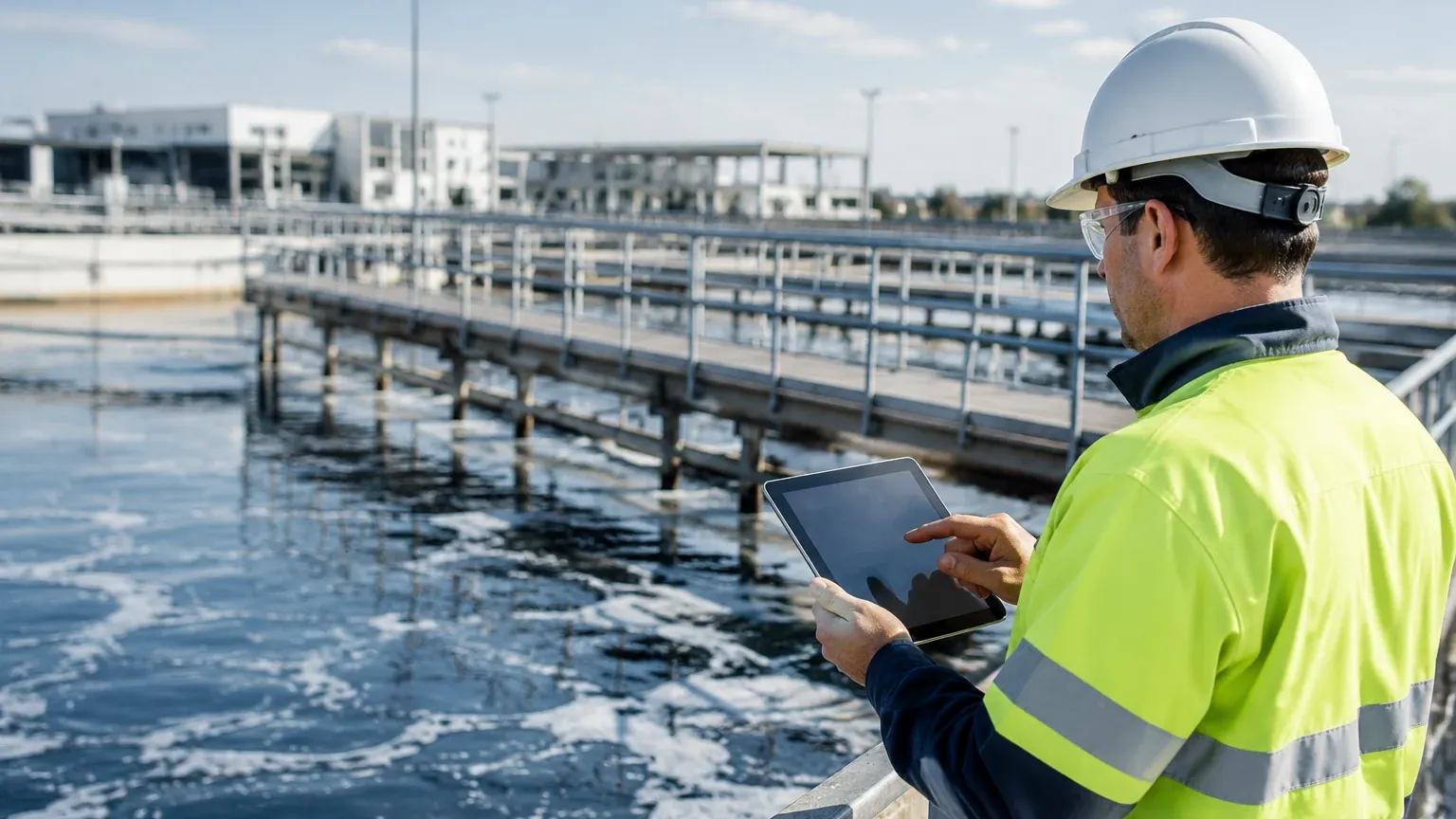
In many B2B industrial environments, flow measurement is only one part of the puzzle. Effective process automation requires the synchronization of flow rates with tank levels and pressure readings. For example, in water treatment plants, the flow rate into a filtration tank must be balanced against the level within the tank to prevent overflow while maintaining optimal throughput.
Welk, as a manufacturer of industrial level measurement instruments, provides the critical "level" component of this equation. While non-invasive flow meters track the movement of fluid through the pipes, radar level meters or ultrasonic level sensors track the volume within the vessels. By combining these data streams, operators can detect leaks (where flow in does not equal level change), monitor pump efficiency, and automate chemical dosing with higher precision.
Frequently Asked Questions
Q: Can non-invasive flow meters work on partially filled pipes?
No, standard clamp-on ultrasonic flow meters require the pipe to be completely full. If the pipe is partially full, the ultrasonic signal will be interrupted by the air-liquid interface, resulting in a signal loss error. For partially filled pipes or open channels, level-based flow measurement using a flume or weir is recommended.
Q: How does pipe scale affect measurement?
Internal scaling or build-up effectively reduces the internal diameter (ID) of the pipe. Since the meter calculates volumetric flow based on the ID programmed by the user, scaling will cause the meter to over-read. Furthermore, heavy scaling can attenuate the ultrasonic signal.
Q: Is it possible to measure the flow of gases non-invasively?
Yes, but it is significantly more challenging than liquid measurement. Gases have much lower acoustic impedance than liquids, making it difficult to couple the signal from the pipe wall into the gas. High-pressure gas applications are more suited for non-invasive measurement than low-pressure systems.
Q: How often do clamp-on meters need recalibration?
Because there are no moving parts and no contact with the fluid, the electronic components are very stable. However, the coupling agent should be inspected periodically (every 1-2 years) to ensure it hasn't degraded or dried out, which could lead to signal degradation.
Conclusion
Non invasive flow measurement represents a significant advancement in industrial instrumentation, offering a blend of flexibility and precision that wetted sensors cannot match. By understanding the nuances of transit-time versus Doppler technology and adhering to strict installation protocols regarding pipe preparation and straight runs, facilities can achieve reliable flow monitoring with minimal operational impact. For those looking to optimize their entire fluid management system, integrating these flow solutions with robust level measurement technology from the Main Page ensures a comprehensive approach to process automation and safety.